
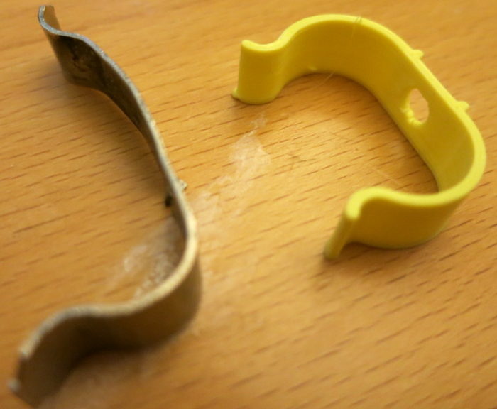
I’ve found 3D printing to be perfect for creating replacement parts for the various things that break around the house. Recently I realized that I could make a replacement for the armoire door clip that had been bent beyond recognition over the years. This post details how I designed and tested the 3D printed replacement, including a checklist at the end of this post.
I started by taking photos of the existing clip and rollers, then using a digital caliper to measure the dimensions of the rollers that the clip needs to snap into.
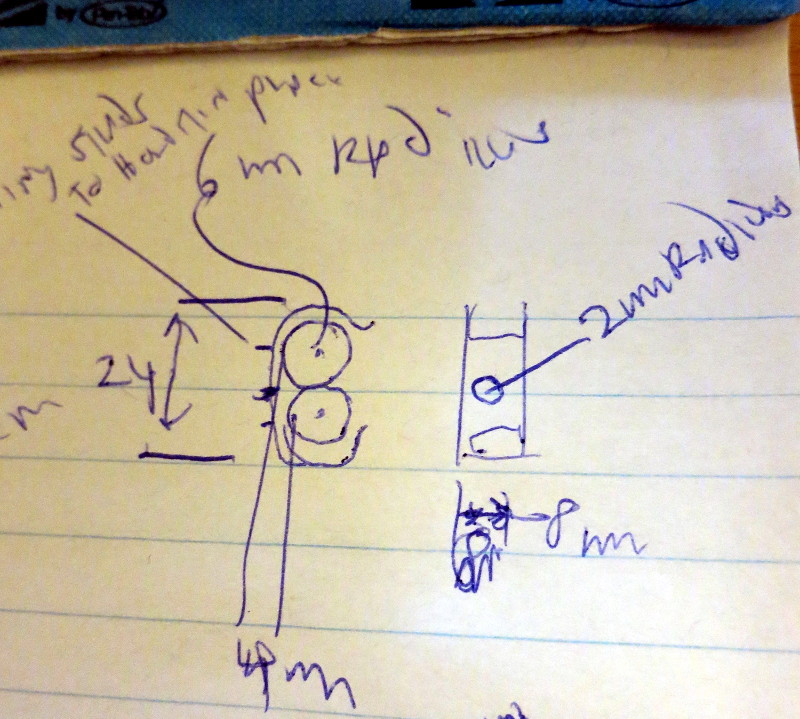
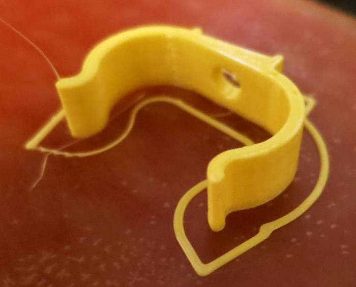
I measured the height of the rollers at 24 mm top to bottom, the diameter of each roller at 12 mm, the width of the original clip at 8 mm, and the diameter of the screw hole in the center of that clip at 4 mm.
I then did a little sketching, and decided a 1 mm thick clip should hold well and still be springy, and that there should be some short (1 mm) studs at the back of the clip to dig into the door a little – to keep the clip from rotating (which was part of why the original metal clip was bent so often).
The point of these rough sketches is to decide how to approach the more formal CAD design.
I then opened FreeCAD and created a first draft in a few steps:
- I created the profile of the clip, and extruded (stretched) that profile into a 3D object.
- I added a hole to the middle. I’ll talk about the hole shape in a minute.
- I made two 1 mm square bars to run horizontally along the back of the clip – to help hold the clip in place.
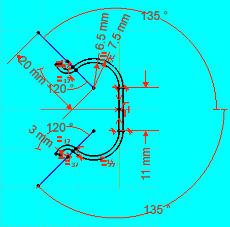
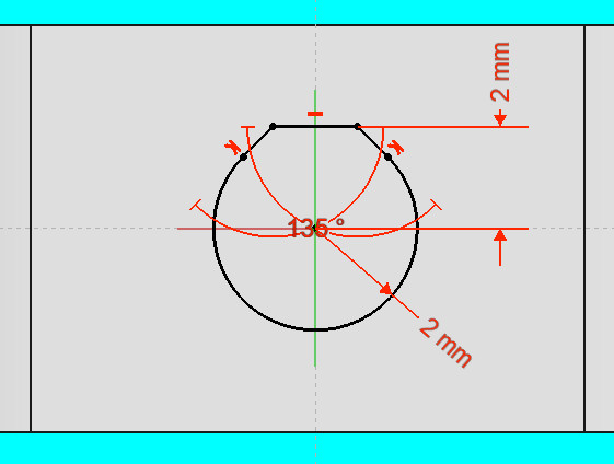
As you can see from the above picture, the screw hole isn’t round. The reason is that I like to print things without support, and this shape hole, printed on its side (as it’s pictured here), will print without support as long as the flat top part is less than about 10 mm. For the 2 mm hole here, the flat top printed fine without support.
I printed this first draft and tried it out.
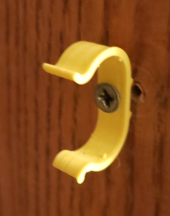
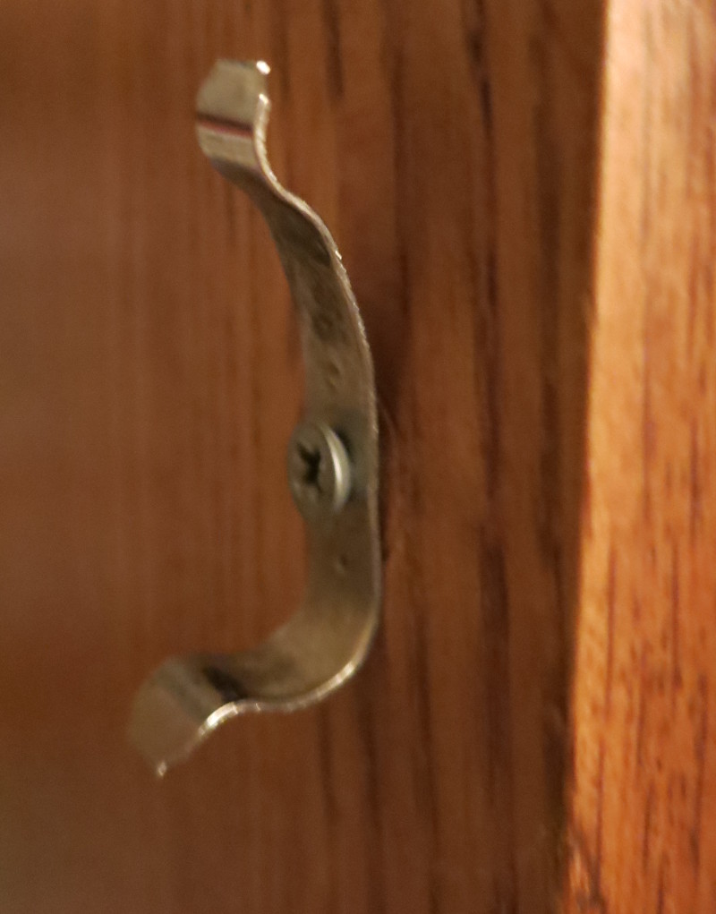
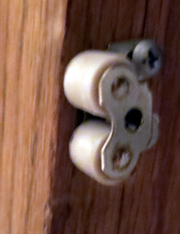
It didn’t hold the door closed. So I took a closer look at the rollers and noticed that the two rollers didn’t line up vertically; the woodworker who made the cabinet had deliberately angled the rollers. This is a good example of making assumptions about the design: I had assumed the rollers would be vertically aligned – why wouldn’t they be?
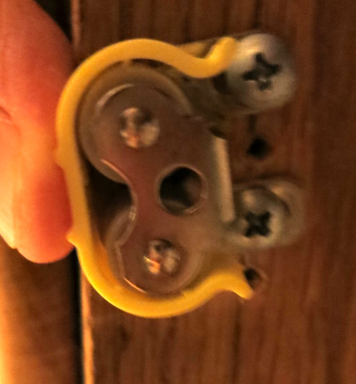
I decided to add a wedge to the back of the clip so that the clip would be at the same angle as the rollers. To measure that angle, I took a photo of the clip pushed onto the rollers (above), then rotated that image in Gimp until the clip seemed vertical. That rotation was about 9 degrees.
I also noticed the clip didn’t hold very well because it was too springy. So I went back to FreeCAD and did two things: 1) added a wedge to the back of the clip, to align it with the rollers, and 2) thickened the clip walls to 1.5 mm.
This second draft worked great! The armoire door closed and opened easily; I even tried slamming it a couple times. I was feeling pretty good, then realized the clip had broken – bummer.
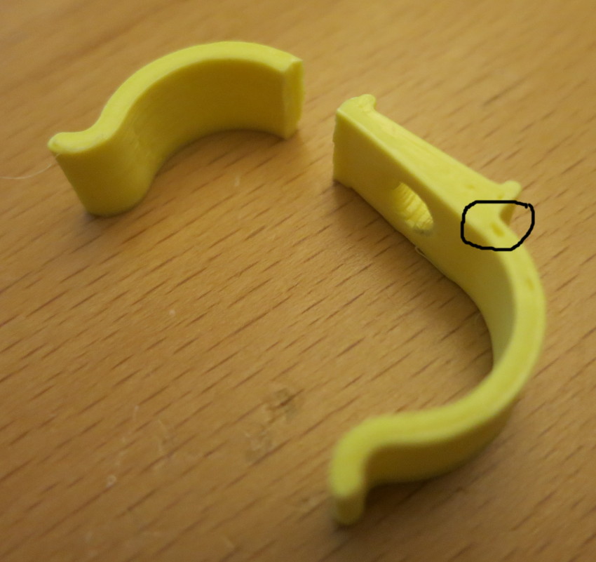
Testing the remaining arm of the clip with my fingers, I saw that one reason the clip broke is that the 1.5 mm clip is much more stiff than the 1 mm clip. I printed all these parts in PLA, which bends but can be brittle.
Looking at the photo above, you can see a second reason the clip broke: a gap in the infill. Infill gaps in mechanical pieces is a topic of its own, well covered in Clifford Smyth’s indispensible book, “Functional Design for 3D Printing“, in the chapter titled “Understanding the slicer”.
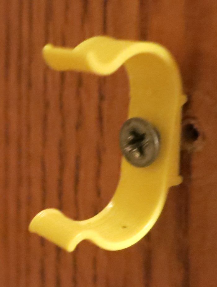
Since the thicker wall was a bit too stiff for my uses, I decided to ignore the infill problem and go back to a 1 mm thick clip, which had had no infill problems. This third and final draft of the clip worked perfectly: the armiore door now stays closed, and is still easy to open.
Total time to replacement: about 1/2 day from the initial idea to the finished clip – the actual design time was closer to a couple hours. Cost: a few cents.
To recap the process I used to replace this bent clip:
- Take photos to study the broken part and its context (what it fits into)
- Make measurements of the critical dimensions of the part and its context. A digital caliper is vital for accurate measurements.
- Sketch the replacement part with pencil and paper.
- Make a first draft in your CAD application, such as FreeCAD, and print a test print.
- See how your first draft design fits. If it works, you’re lucky! If not, take more photos and make notes to understand what you need to change.
- Edit your CAD model to adjust it, then print a test print and see how this second draft fits. Repeat steps 5 and 6 as needed.
- Celebrate, and post what you learned.