
I’ve been doing a bit of mechanical work on the lunar clock, that I started in my previous post.
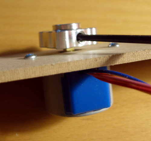
As a prototype to help me design the laser-cut parts, I cut out a strip of 1/8″ MDF, cut a square for the motor’s shaft and two holes for the motor mounting holes, then mounted the motor to that strip of wood.
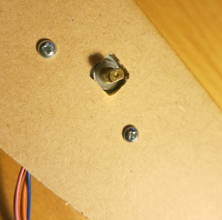
With the motor fastened, I placed the hub on the shaft, making sure to provide a little clearance so the hub won’t rub against the wood. The hub will hold the wheel of lunar images.
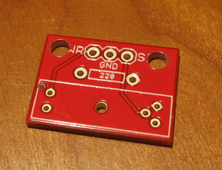
Turning to the photo-interrupter that will detect the slot in the lunar wheel, the photo-interrupter breakout board from Sparkfun, fine product though it is, lacks mounting holes. …so I added some.
Looking at the breakout board, it seemed likely that I could add holes at the corners of the board, near the text “PWR” and “SIG”.
Drilling the holes and testing the board proved it out: nothing untoward happened to the board’s circuit, other than connecting the mounting holes to the ground plane of the board.
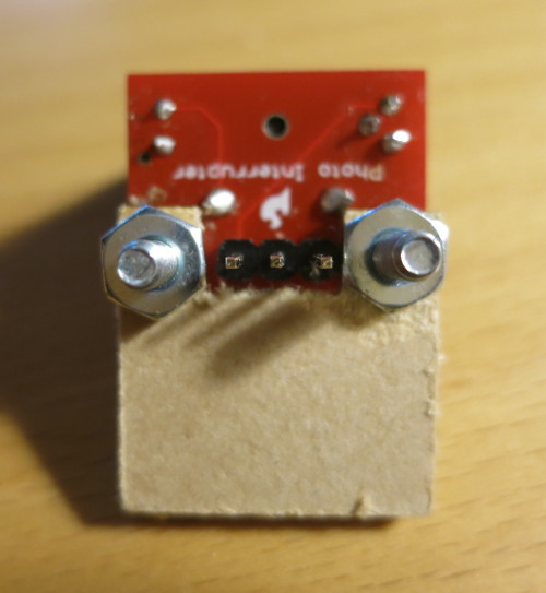
I then soldered the parts onto the breakout board and used the holes to mount the board to a scrap of MDF, for testing.
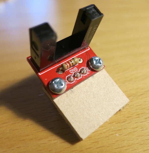
Notice that the screw heads are low, to keep from interfering with the photo interrupter, and the scrap board is mounted underneath the breakout board, to keep the parts away from the lunar wheel which will pass through the photo-interrupter.
Notice that on the flip side, I had to align the nuts so they wouldn’t interfere with the pins on the back of the board.
My plan is to design laser-cut parts to mount the photo-interrupter and the stepper motor. Here’s how the photo-interrupter should align with the lunar wheel.
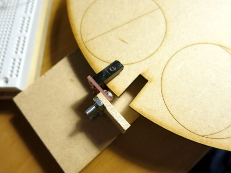
I am a bit puzzled about how to mount the photo-interrupter to the board. My current plan is to use a small right-angle bracket to fasten the parts.