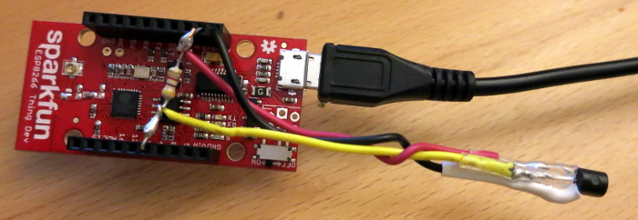
Today’s post is a How-To for a project I recently completed: a temperature-only Weather Underground Personal Weather Station made from an ESP8266, a MAX31820 temperature sensor, and a few miscellaneous parts. The whole project fits inside a 3D printed project box for mounting on an exterior wall that is sheltered from the weather.
In my previous post, I designed a 3D printed sensor junction box for my well tank depth sensing project. In this post I solder… a lot.
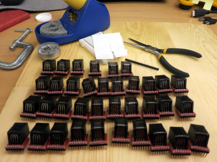
I have 36 RJ45 jacks, 36 breakout boards for those jacks, and a pile of break-off headers for those breakout boards. Each breakout board has 8 holes for the RJ45 jack pins and 8 more holes for the header pins. That’s 36 * (8+8) connections I need to make to attach the breakout boards to the jacks. That’s 576 connections to solder!
I’ve begun another Arduino/ESP8266 project: reporting the level of water in our well tank. This project will involve the ESP8266, MAX31820 temperature sensors, some mechanical work, sending data to a web-based database, and interpreting the temperature data to estimate the well water level.
I have to confess that sometimes I need a push to make the right design choice.
It’s been a long time – way too long – since I worked on my Lunar Clock project. In the meantime, Sparkfun has introduced new, inexpensive microcontrollers aimed at Internet-of-Things applications. I knew one of those new microcontrollers would be perfect for the Lunar Clock, but I dragged my feet.
Then one day, a Github user pointed out that one of the boards I was using has been obsoleted.
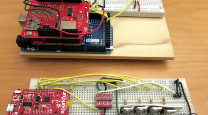
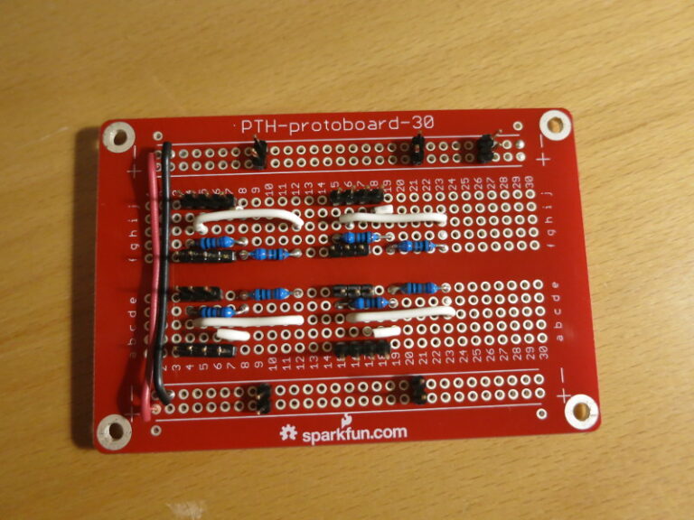
In my previous post I described how to use long break-away headers, and started soldering the circuit together. In this post I finish transferring the scale circuit from the breadboard to a protoboard, and do a quick test mount of the circuit on the plywood scale base.
A reminder: I found that the Load Cell Amplifier was (by design) so sensitive to changes in resistance that just touching the resistors on my solderless breadboard caused large changes in the Amplifier output. So I wanted to solder all the parts down.
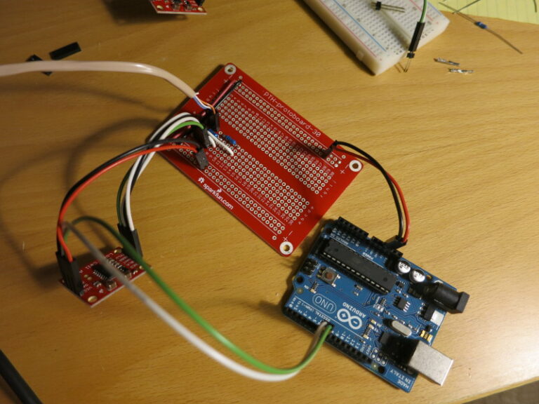
It’s a good time to recap: This project is a scale that will sit underneath my dog Pippa’s bed, so that I can measure her weight automatically, at night while she sleeps. The project-in-progress is Open Source, at my CurieBLEWeightMonitor Github repository.
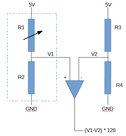
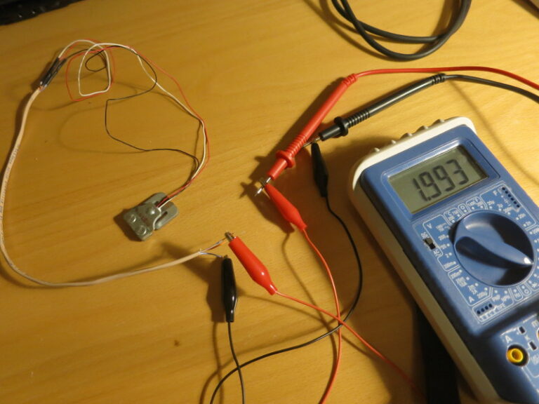
In my previous post I covered how to choose matching resistors for the Load Sensor to convert the Load Sensor into a Load Cell that can be wired into Sparkfun’s Load Cell Amplifier. In this post, I nearly finish building the breadboarded circuit and start transferring it to a soldered protoboard.
In my previous post, I worked through the calculations of weight and center of gravity when using four Load Cell Amplifiers instead of one. In this post, I build the circuit for the first of the four Load Sensor / Load Cell Amplifier combinations I’ll be using.
I’ve stored my Robotic Glockenspiel on its side since I finished it in April (it’s huge). The other day I opened the lid and found, to my horror, that the breadboard had completely pulled away from its adhesive pad – only the wires are keeping the breadboard from falling off completely!
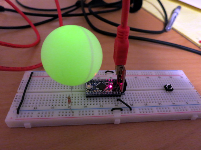
Some time ago I read that you can use a ping pong ball to soften the harsh light of an LED, so I thought I’d try it out.
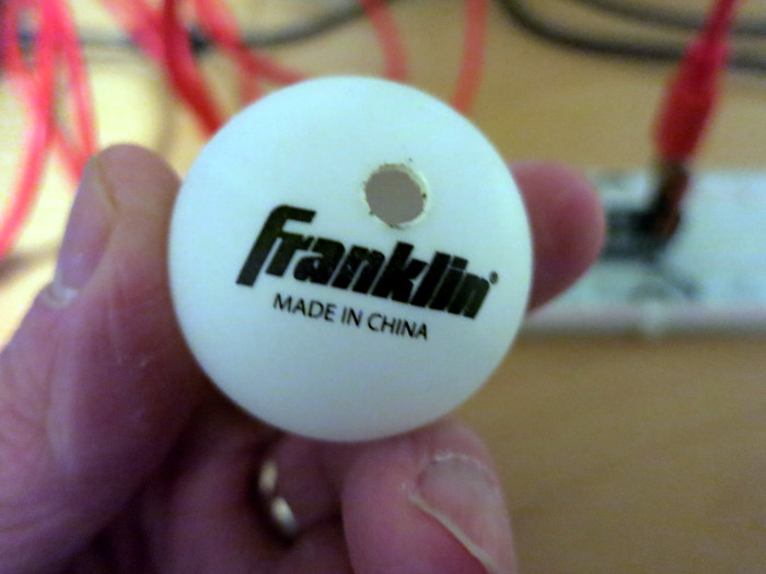
Step 0: pick out a white ping pong ball. I used a standard 40mm ball; I could have used a 35mm Foosball instead.
Step 1: make a hole in the ping pong ball to hold your LED. For a 5mm LED, an ice pick heated on a stove top is an handy tool for making that hole. I haven’t tried a drill press, but that seems another possibility.
Ping Pong ball with hole for LED
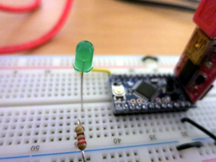
Step 2: set up a circuit to blink an LED, perhaps using an Arduino Pro Mini.
LED ready for the ping pong ball diffuser
Step 3: press the ping pong ball onto the LED. For a more permanent mechanical connection, you could glue the LED into the ping pong ball using a hot glue gun.
Step 4: Enjoy the magical, diffuse light of the LED in the ping pong ball. You may need to turn out the lights to see it well. Have a look at my Blinking Ping Pong Ball LED video of the result.
So a ping pong ball really is a quick and easy light diffuser for your LEDs – disco time! …or you can paint pupils on them to create blinking night-creature eyes as in this Hidden Creatures Arduino & LED Blinking Eyes Kit video.