In my previous post, I designed and printed a Centering Guide to line up the top and bottom pieces of the scale. In this post, I finish assembling the scale.
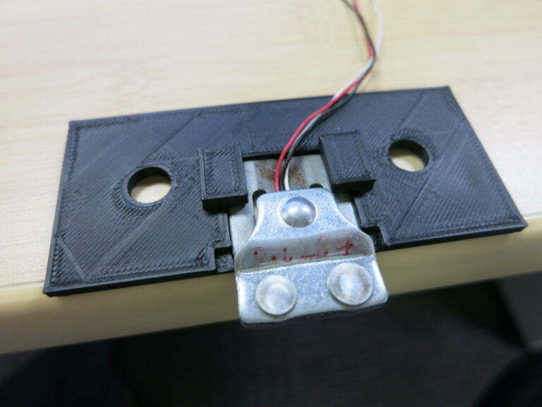
Now that I have the Load Sensor Holders that I designed and printed, I drilled mounting holes in the blocks that will hold the Load Sensors.
Continue reading Dog Weight Scale Part 13: Load Sensor Mounting and Final Assembly →
In my previous post, I did a little woodworking on the scale. In this post, I start designing a 3D printed part that will keep the top of the scale centered on the bottom.
Ever since I measured the center of gravity of the top plywood circle, I’ve been puzzling through how to make sure that center of gravity stays centered on the bottom part of the scale. Without some sort of connection between the top and bottom plywood circles, the top will inevitably slide over time, messing up all the center of gravity calculations. On the other hand, if this connection between the top and bottom has much vertical friction, it will take some of the load of the scale, throwing off the weight calculation.
Continue reading Dog Weight Scale Part 12: More 3D Printing →
In my previous post, I 3D printed parts to hold down the Load Sensors. In this post, I correct the counterbored holes that keep the nuts from protruding below the bottom of the bottom piece of plywood.
In the woodworking post, I used a router to cut counterbore holes on the bottom side of the bottom piece of plywood. These holes hold the nuts that hold the circuit boards.
Continue reading Dog Weight Scale Part 11: Routing Counterbore Holes →
In my previous post I soldered the weight scale parts to a proto-board. In this post, I design and 3D-print the part that keeps the Load Sensors from slipping.
The Load Sensor is an oddly-shaped thing that has a few tricky constraints: the T-shaped part in the middle must be free to bend downward (my wooden mounts take care of that), and I don’t want it to slide out of place horizontally or tilt off of its position when I’m putting the top plywood piece on the scale.
Continue reading Dog Weight Scale Part 10: 3D Printing Load Sensor Holders →
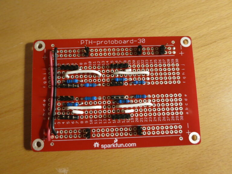
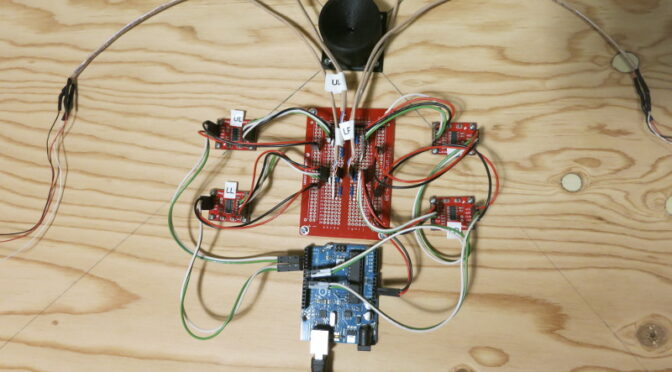
In my previous post I described how to use long break-away headers, and started soldering the circuit together. In this post I finish transferring the scale circuit from the breadboard to a protoboard, and do a quick test mount of the circuit on the plywood scale base.
A reminder: I found that the Load Cell Amplifier was (by design) so sensitive to changes in resistance that just touching the resistors on my solderless breadboard caused large changes in the Amplifier output. So I wanted to solder all the parts down.
Continue reading Dog Weight Scale Part 9: Soldering the V2 Circuit Together →
Technical Writing and Self-Pubilshing
