
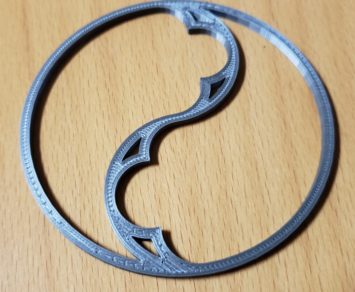
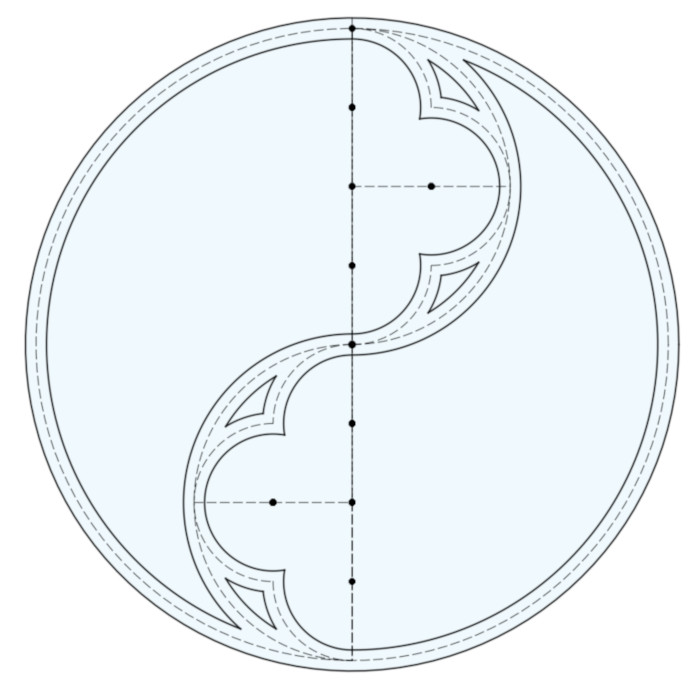
If you’re interested in Gothic architecture, you may have seen my post on Designing a Gothic Trefoil. In this post I walk you though the design of a simpler ornament: the Gothic Duefoil: a circle divided into two arches, which are themselves each divided into three lobes.
I assume you’ve learned the basics of Geometric Construction with a pair of compasses and ruler, for example how to create a line perpendicular to another, how to bisect an angle, how to construct a circle tangent to two lines and touching a point, etc. You don’t have to know how to do these operations, but knowing how will help you understand how and why the Duefoil is constructed the way it is.
I created this Duefoil using Autodesk Fusion 360. If you instead use the free, Open Source CAD program FreeCAD, you may want to read my post on Designing a Gothic Duefoil in FreeCAD.
In the process of creating this design I found that Fusion 360 – like any Computer Aided Design application – has a few quirks, the main one being that Fusion 360 runs much faster if you simplify the constraints in your model. I’ll discuss each of these simplifications as we go along.
The Basic Design: It Begins With a Circle
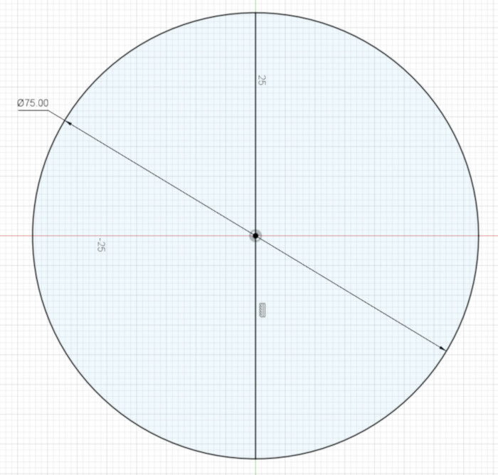
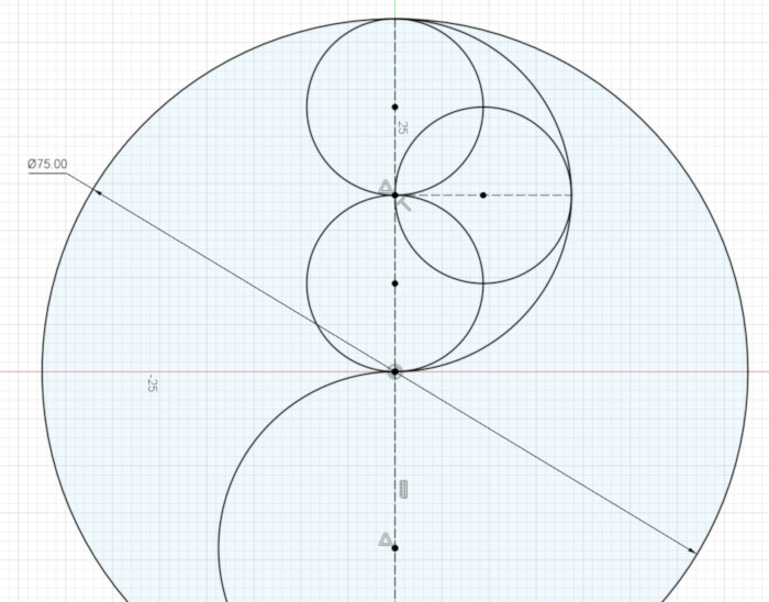
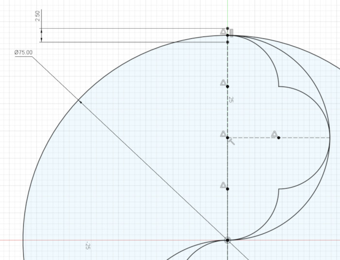
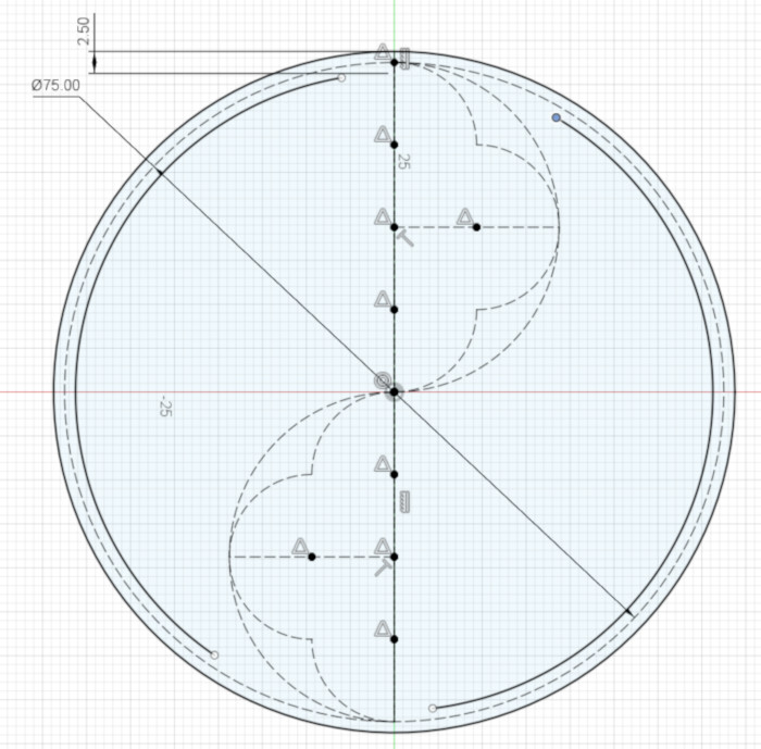
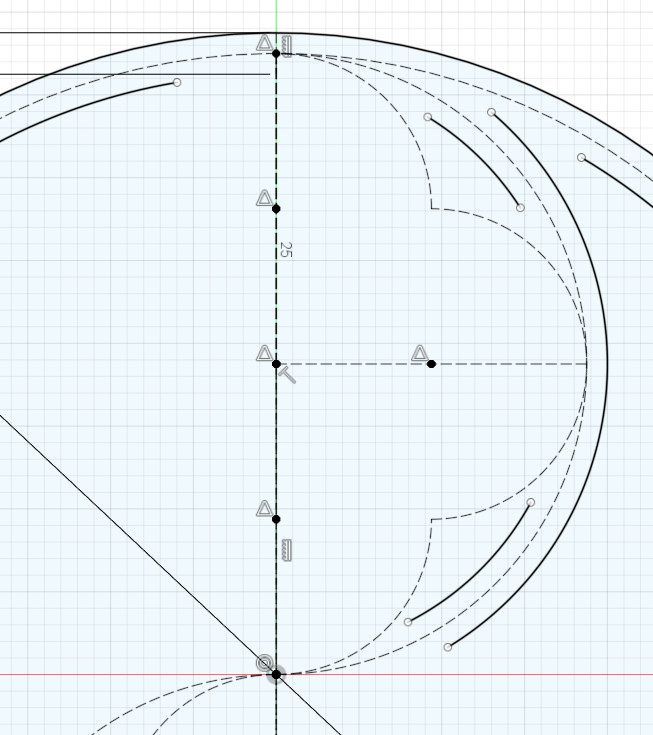
Create a circle, centered on the origin (the center of the XY plane). Pick a size for your circle; I made mine 75 mm in diameter.
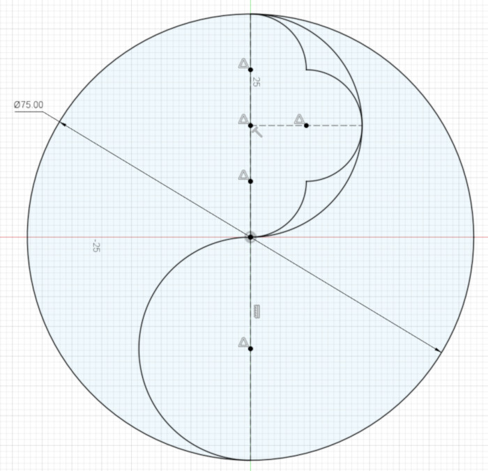
We want to constrain our design to not rotate, so put a vertical line through the circle’s center, with each end of the line touching the edge of the circle. These few Constraints should cause Fusion 360 to say this Sketch is a Fully Constrained Sketch, or one that has zero degrees of freedom. That is, there is only one possible circle and line that can satisfy the constraints you’ve created.
The Trefoil is based on fitting three (“tre” = 3) tangent (touching) circles into the larger circle; in contrast, our duefoil (“due” = 2) is based on two tangent circles.
Don’t add any circles yet; the figure below simply illustrates this underlying division into two tangent circles:
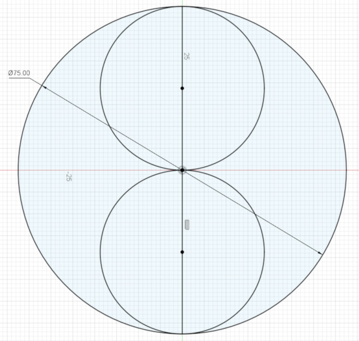
Notice that the centers of these two circles – the centers of the semicircles we’re going to create – are each half way between the center of the large circle and the outside of the large circle.
Now we come to our first Fusion 360 simplification of the design: although Fusion 360 is perfectly capable of calculating the semicircle’s center given a few constraints, it’s happier (quicker as constraints pile up) if we tell it the location of those centers.
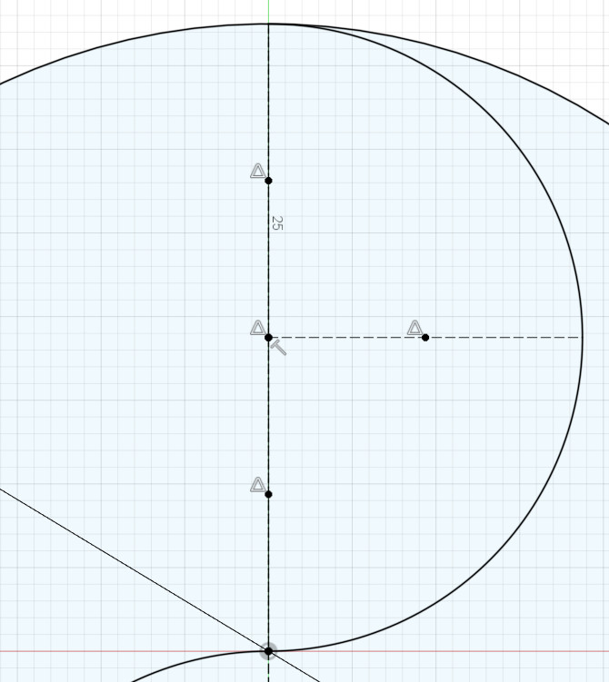
To set the center points of the two semicircles, we’ll divide the vertical line into quarters. Because that line is already divided in half by the large circle’s center point, we’ll divide each half of the line in two.
Create two construction lines, and add a point at the midpoint of each line.
Make one end point of each line Coincident with the center of the circle, and the other end point of each line Coincident with an end point of the vertical line.
Gothic design is based on tangent (touching) arcs. In this case, make each semicircle tangent to the larger circle, at the end of the vertical line, and Tangent to the center of the larger circle.
Here is another Fusion 360 simplification of the design: instead of making the inner end points of the semicircles Coincident with the large circle’s center point, we’ll make each of those end points Coincident with the vertical line. We do this because it’s mathematically simpler – I’m not exactly sure why – for Fusion 360 to calculate where an arc intersects with a line than it is to calculate an arc’s intersection with a point.
One way to think about this complexity is to think about drawing the arc by hand: if your arc’s radius is a little too big or small, it’s easy for your arc to miss the point you’re aiming for; on the other hand, drawing the arc until it hits a line is a lot more forgiving of errors. In the same way, Fusion 360 has less to think about if it’s just drawing an arc until it intersects a line.
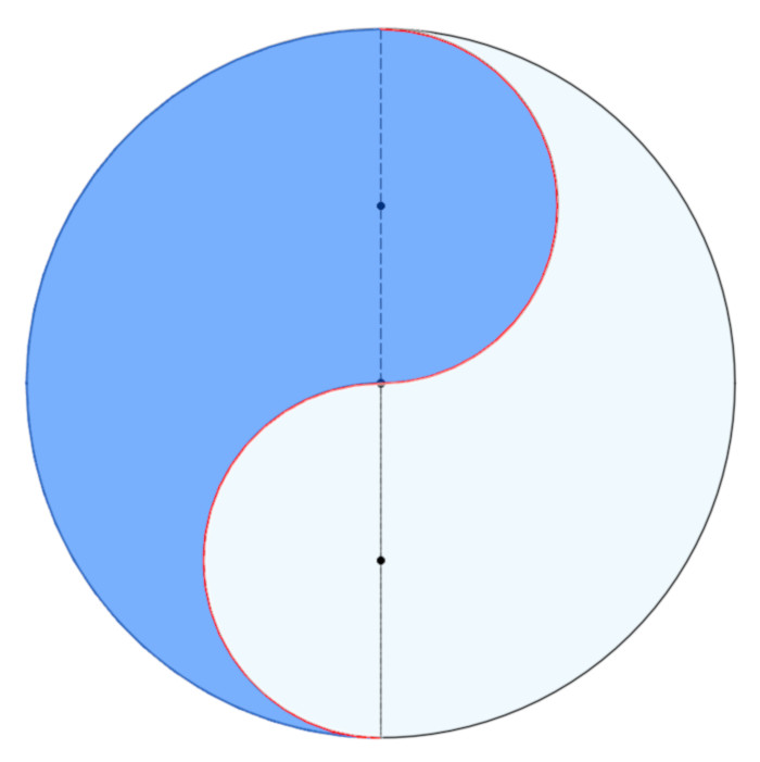
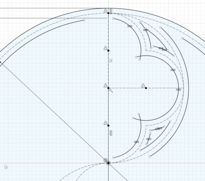
Now that you’ve constructed the two semicircles, you can see the Duefoil is based on the familiar Yin and Yang symbol.
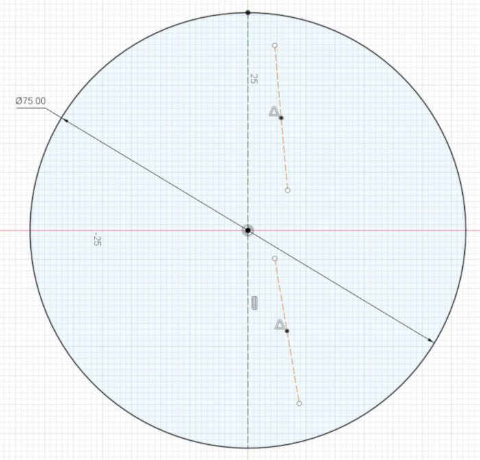
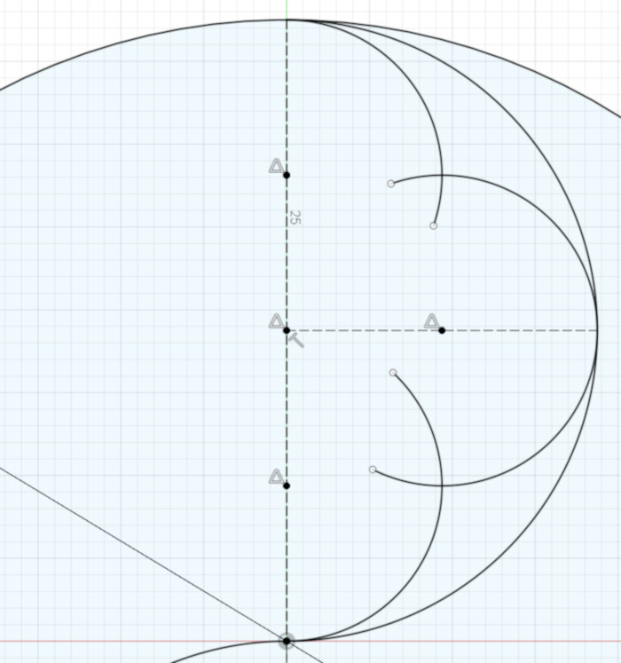
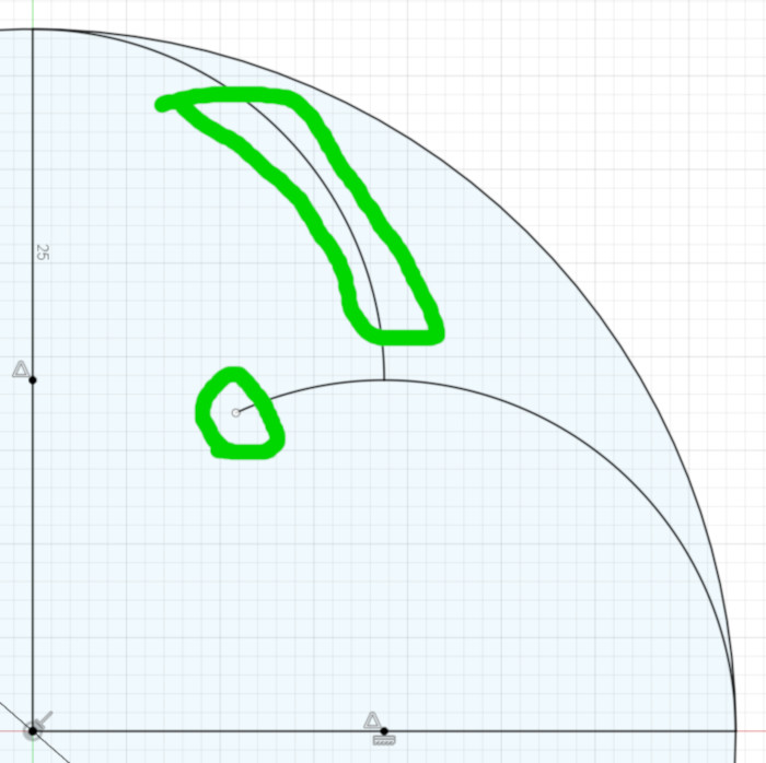
To create the pointed ornaments inside each semicircle, we’ll create three equal-sized, intersecting (not tangent) arcs inside each semicircle.
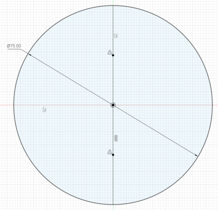
Again, don’t add three circles yet; the figure below simply illustrates this division into three equal, overlapping circles:
To divide the upper semicircle’s vertical line into quarters, use the same technique you used earlier: create two construction lines, add a point to the middle of each, then make the endpoints of those lines coincident with the center of the semicircle and the ends of the lines coincident with the ends of the semicircle’s vertical line.
To mark what will be the center of the middle arc, first create a horizontal line (one perpendicular to the vertical line) whose one end is coincident the center of the semicircle and whose other end is coincident with the semicircle.
Now add a point at the middle of that horizontal line you just now created. That point will be the center of the middle arc.
Next, create three arcs:
The top and bottom arcs are centered on the center points of the vertical lines. They start at one of the the vertical lines’ endpoints, and – if extended – would go through the center of the semicircle.
For example, the center of the uppermost arc is coincident with the center of the upper vertical line, one end of that arc is coincident with the upper end point of that vertical line, where it meets the edge of the semicircle, and, to simplify things for Fusion 360, the arc – not its end point – is coincident with the vertical line rather than the center of the semicircle. Those constraints leave only one thing about the arc unconstrained: its inner end point. We’ll take care of that in a minute.
The center arc’s center is on the center of the horizontal line, and that arc is coincident with the right end point of that line. Both of that arc’s end points are unconstrained for now.
These constraints are enough to make the arcs equal sized. If you like, as an exercise you can write out a geometric proof to show that the three arcs have the same radius.
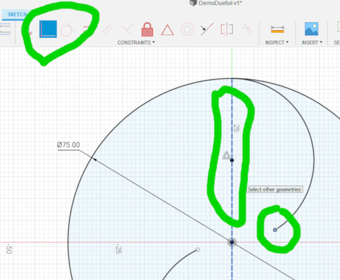
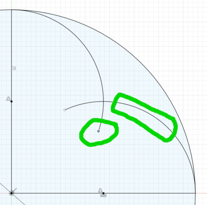
Next, all we have to do is make each arc end at the intersection with its overlapping arc. Here we come to another simplification for Fusion 360.
My first instinct was to simply make the end point of one arc coincident with the end point of the overlapping arc. Unfortunately, I found that doing that for every pair of intersecting arcs in the design made Fusion 360 slower and slower as the design progressed. By the time I was half way through the thickening of the lines (see below), Fusion 360 was taking over 10 seconds to calculate the intersection of two arcs.
So, we have another Fusion 360 simplification: whenever you want two arcs to end at their intersection, first make the end point of the first arc coincident with the second arc – not the second arc’s end point – then make the end point of the second arc coincident with the first arc – not that arc’s end point.
The result is the same as making the two arcs’ end points coincident, but Fusion 360 calculates the intersection of an arc’s end point and an arc much quicker than the intersection of two arcs’ end points. See the following figures for an example of creating this intersection:
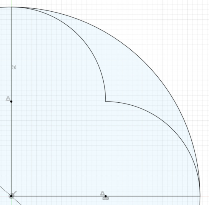
Once you’ve set the intersections of those three arcs inside the semicircle, you’re half finished with the basic design of the duefoil.
Next divide the other semicircle in the same way, with three equal-sized arcs.
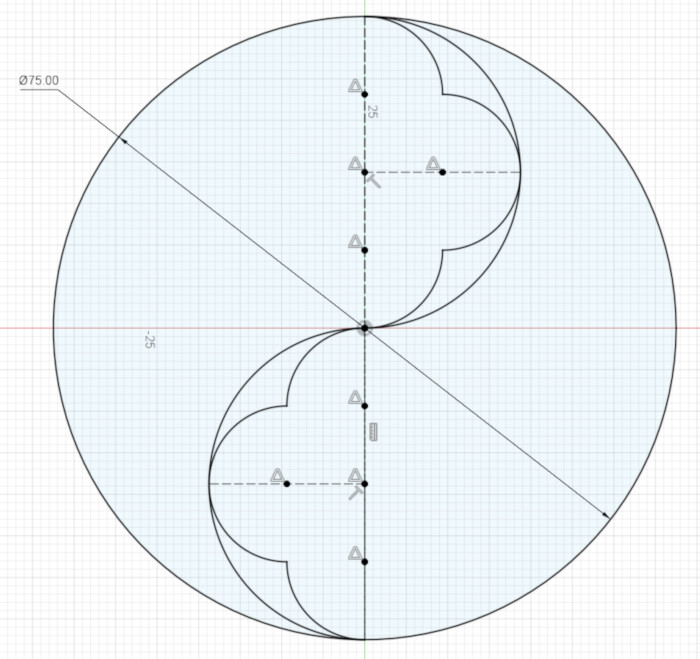
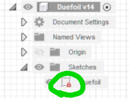
Fusion 360 should now indicate that your Sketch is Fully Constrained (showing the little red lock). If not, you’ve made a mistake somewhere that it’s best to fix now rather than later.
You now have finished the basic structure of your duefoil. Congratulations!
Thickening the Basic Design
Right now your duefoil consists of infinitely-thin lines. Instead, you probably want a design that has some thickness, so it can be 3D printed, cut with a CNC machine, cut out with a scrollsaw, or painted onto a notebook cover. To thicken the duefoil, we’re going to create inner and outer arcs for every arc and circle in the original design.
This part is a little more complicated, so it will help to first get a glimpse of what we’re going to create:
First, change each line and arc in the current design into a Construction (dotted) line. In Fusion 360, I changed each part using the Normal/Construction right-click-menu item.
You may have noticed that in constructing the basic duefoil design, we used only one measurement: the 75 mm diameter of the outer circle. That’s because the original Gothic designs were based on geometric construction that doesn’t use the markings on a ruler.
To keep to that goal, of using as few measurements as possible, next you’re going to create one little ruler to thicken the lines.
Create a vertical line that has a point in its middle, and whose length is the thickness of your design. I chose my 75 mm diameter duefoil to have a thickness of 2.5 mm. Also change your ruler from a Normal line to a Construction line.
Next make the center point of the ruler coincident with the top end point of the duefoil’s main vertical line. Now you have a fully-constrained ruler whose end points are fastened to the duefoil design.
Next, create a circle whose center is coincident with the center of the main circle, and which is coincident – that is, goes through – the top endpoint of your ruler. That circle forms the outside of the thickened main circle.
Now create two arcs that will become the inside of the thickened main circle. We create arcs instead of a circle because those arcs will intersect with other parts of the thickened design. Make each arc’s center coincident with the center of the main circle, and make the arc coincident with the bottom end point of your ruler; that is the radius of each arc is the distance between the center of the main circle and the bottom end point of our ruler.
We can’t yet constrain the end points of these inside arcs, because we haven’t yet drawn the lines they will intersect with.
Next, create the one outer and two inner arcs for the top semicircle. Use your ruler’s end points to constrain the arcs’ radii, as you did for the large circle’s edges. Again, we can’t constrain the endpoints of these arcs just yet.
Next we’ll create the inner and outer arcs for the three smallest arcs in the design.
Now is the point where things get a little tricky: you can use your ruler, as before, for setting the radii of the inner and outer arcs for the topmost of the three arcs, but the middle and bottom arcs are too far away from the ruler to use it; that is, they don’t intersect with the ends of the ruler.
Fortunately in this design the three smallest arcs in the basic design have the same radii (size). That means that their thickened versions also have the same radii; for example, the inner arc for the center arc of the basic design has the same radius as the inner arc for the top arc of the basic design. Most CAD applications have a way to constrain one arc’s radius to be equal to another’s.
Now it’s a simple matter to join most of the endpoints of the new arcs. In Fusion 360 I again used the trick of creating coincident arc end points by making one arc’s end point coincident with the other arc, then making the other arc’s end point coincident with the first arc.
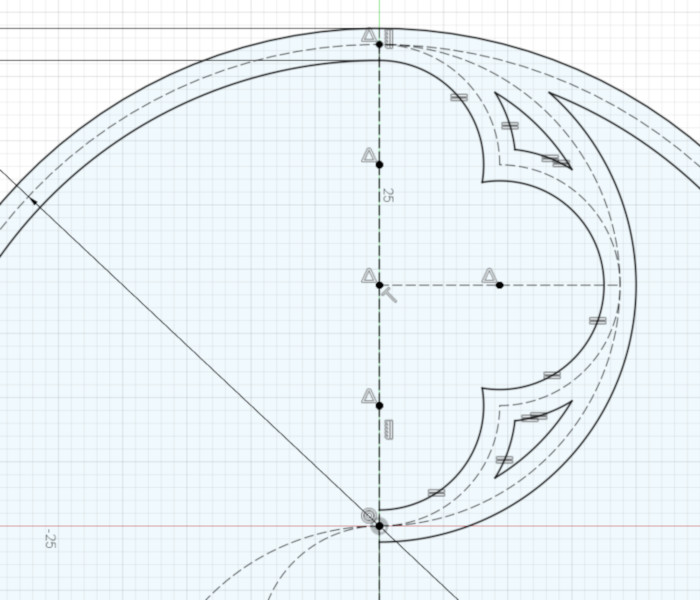
At this point, you have thickened all the arcs in the top half of the design. Next, thicken all the arcs in the bottom half of the design, using that trick of constraining an arc’s radius to be equal to a similar arc from the other half of the design.
Once you’ve done that, all you have left is to connect the few remaining arcs to each other – and you’re done!

Making the 2D Design 3D Printable
Now that you have a 2D design, you can use it in a 3D printable design in a couple ways:
- You can emboss it onto a flat object by selecting the thickened 2D design and Extruding it (stretching it in the 3rd dimension), then joining the resulting object to the flat surface.
- You can engrave it into a flat object by Extruding it as before, then Subracting (or Cutting) it from the flat object.
- You can stencil it through a flat surface by Extruding the open parts of the design – the two swooping voids and the four sort-of-triangular spaces – then Cutting those extruded objects from the flat surface.
- You can make it a standalone object – such as a hanging ornament – by just Extruding it and printing the resulting 3D object.
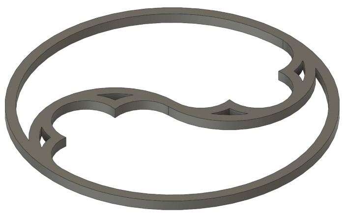
Because the design is constraints-based, you can easily change the thickness of the whole design or the size of the whole design by changing the measurement of your ruler from 2.5 mm to something else, or changing the diameter of the main circle from 75 mm to something else.
P.S., I have to confess I made up the name Duefoil based on the name Trefoil, Quatrefoil, and Cinquefoil – I haven’t yet found the name of this traditional design. If you know of a good reference for names of Gothic Tracery design elements, please let me know.