
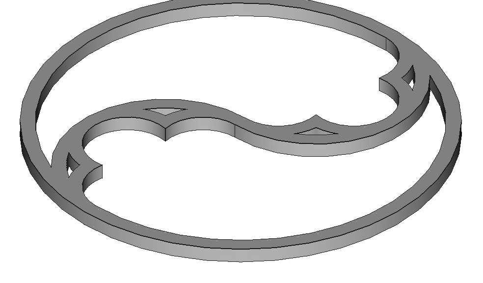
If you’re interested in Gothic architecture, you may have seen my post on Designing a Gothic Trefoil. In this post I walk you though the design in FreeCAD of a simpler ornament, the Gothic Duefoil: a circle divided into two arches, which are themselves each divided into three lobes.
I assume you’ve learned the basics of Geometric Construction with a pair of compasses and ruler, for example how to create a line perpendicular to another, how to bisect an angle, how to construct a circle tangent to two lines and touching a point, etc. You don’t have to know how to do these operations, but knowing how will help you understand how and why I constructed the Duefoil the way I did.
I created this design using FreeCAD, a free, Open Source, Computer Aided Design (CAD) application. If you instead use Autodesk Fusion 360, you’ll probably want to read my post Designing a Gothic Duefoil in Fusion 360.
You can download my duefoil FreeCAD design file and the STL file from Cults3D.
Now that I’ve created this design in both FreeCAD and Fusion 360, I found that – at least as of this writing – FreeCAD worked much better for my Gothic designs. Fusion 360 – at least with my novice’s knowledge of it – tended to slow down considerably as I added more and more tangent (touching) arcs.
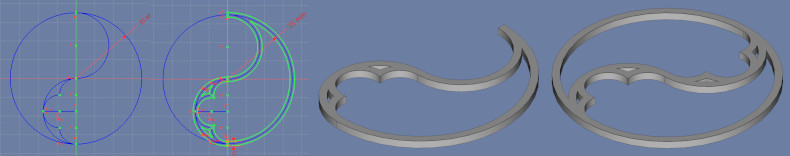
The workflow here will be to create a line-drawing of half of the duefoil, using Construction Lines and Arcs, then ‘thickening’ that design with Normal Lines and Arcs, then extruding the resulting Sketch to form half of the 3D duefoil, then duplicating that half to form the whole duefoil.
By the way, the Gothic Trefoil is based on fitting three (“tre” = 3) tangent (touching) circles into the larger circle; in contrast, our duefoil (“due” = 2) is based on two tangent circles.
The Basic Design: It Begins With a Construction Circle
I assume you know the basics of FreeCAD, so I won’t go into a lot of detail in how to operate that application; there are plenty of tutorials by the FreeCAD community and Help files to get you started.
Begin by creating a new File, and a new Sketch in that file, based on the XY plane.
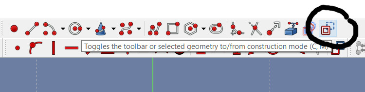
Then, in the Sketcher Workbench, go into Construction Mode: click the Icon that has the hint text “Toggles the toolbar or selected geometry to/from construction mode”. The Sketcher line, arc, etc. tools should change from white to blue, indicating that the lines, arcs, etc. that you create will be Construction lines rather than Normal lines. Construction lines won’t appear in the finished Sketch.
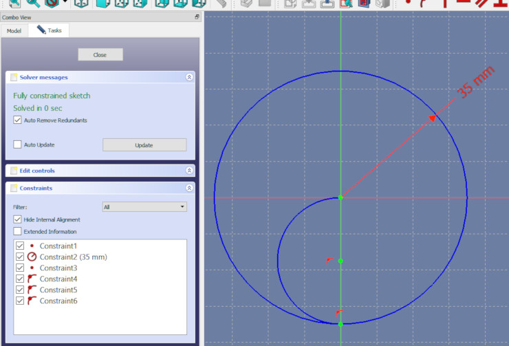
Create a circle, centered on the origin (the center of the XY plane). Pick a size for your circle; I made mine with a radius of 35 mm (70 mm diameter). FreeCAD should draw the circle in blue, which indicates it’s a Construction circle rather than a Normal (white) circle.
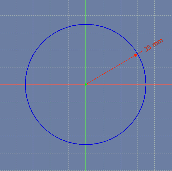
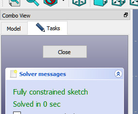
This center (0, 0) and Radius constraint (of 35 mm) should cause FreeCAD to say this Sketch is a Fully constrained sketch, or one that has zero degrees of freedom. That is, there is only one possible circle that can satisfy the constraints you’ve created.
I prefer making my designs fully constrained, and to make them fully constrained as often as possible during the design process. I’ve learned that if I leave something unconstrained until late in the design, it can be hard to find which constraint is missing.
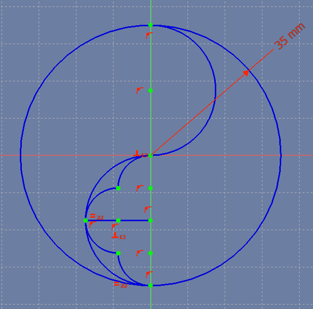
Don’t add any circles yet; the figure below simply illustrates the underlying division of the large circle into two (“due”) tangent circles:

Use the center-and-endpoints arc tool to create a semicircular arc (a half-circle), then constrain that arc in the following ways:
- Constrain the center of the arc to be fixed on the vertical center-line (the Y axis).
- Constrain the upper endpoint of the arc to be coincident with the center of the larger circle.
- Constrain the lower endpoint of the arc to be fixed on the vertical center-line.
- Finally, constrain that lower endpoint of the arc to be also fixed on the larger circle.
These four constraints should make the Sketch Fully Constrained again.
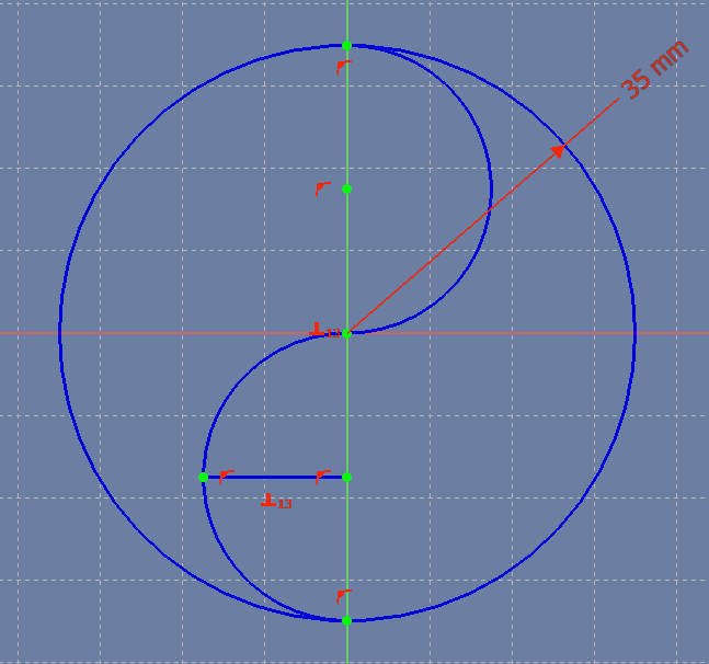
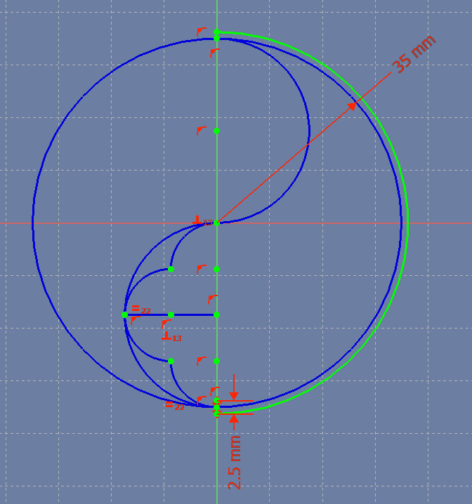
Now use the center-and-endpoints arc tool to create a second semicircular arc, in the upper half of the larger circle. Constrain this arc in a similar way to how you constrained the first arc. Notice that the two arcs form a Yin and Yang symbol.

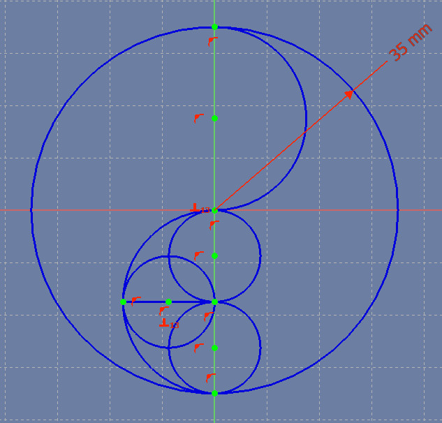
To create the pointed ornaments inside the lower semicircle, we’ll create three equal-sized, intersecting (not tangent) arcs inside the semicircle.
Again, don’t add three circles; the figure below simply illustrates this division into three equal, overlapping circles:
Create a line anywhere in the lower semicircle, then add the following constraints:
- Constrain the right endpoint of the line to be fixed on the vertical center-line.
- Constrain the left endpoint of the line to be fixed on the lower semicircle (where exactly doesn’t matter yet).
- Constrain the line to be perpendicular to the vertical center-line.
That set of constraints should make the Sketch fully constrained again. Notice that the new line cuts the lower semicircle in half.
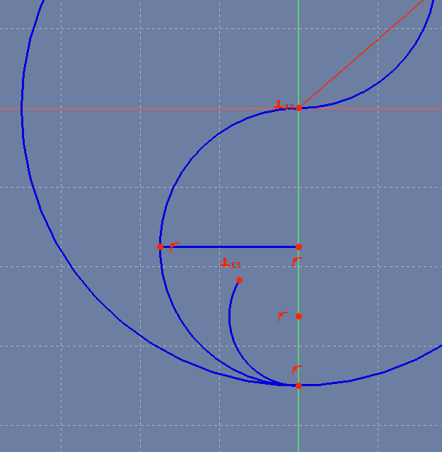
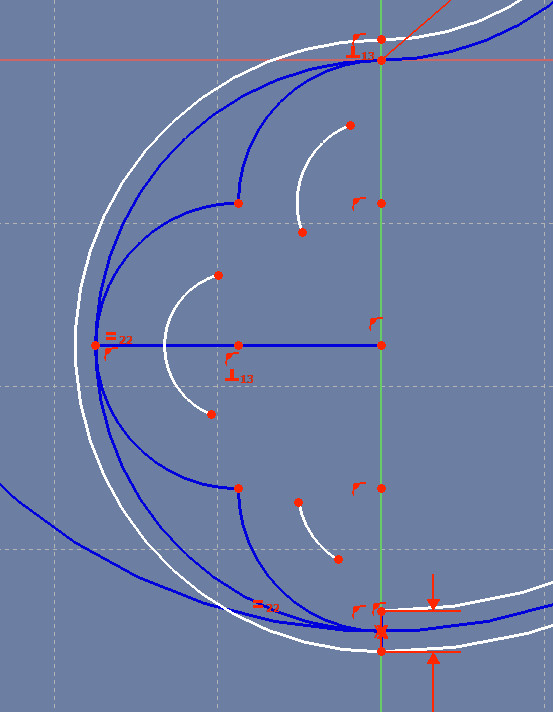
Create the lower arc within the semicircle: Create an arc and add the following constraints:
- Constrain the center of the arc to be fixed on the vertical center-line.
- Constrain the lower endpoint of the arc to be coincident with the semicircle’s lower endpoint
- Constrain the center of the larger circle to be fixed on the newly-created arc. This constraint will make the arc radius the right size to – if extended – intersect the center of the circle.
FreeCAD should now say that the Sketch has 1 degree of freedom. That’s true because we haven’t yet constrained the upper endpoint of the new arc. We’ll add that constraint later.
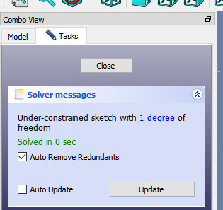
Now create an upper arc in the lower semicircle, constrained like the first arc:
- Constrain the center of the arc to be fixed on the vertical center-line.
- Constrain the upper endpoint of the arc to be coincident with the center of the larger circle.
- Constrain the center of the semicircular arc to be fixed on the newly-created arc. This constraint will make the new arc’s radius the right size to – if extended – intersect the center of the semicircle.
Now you should have two small arcs, one endpoint of each arc can be moved freely, and FreeCAD should say the Sketch has 2 degrees of freedom.
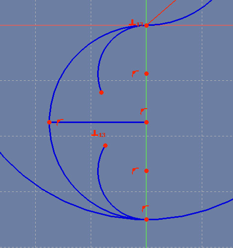
Now create a third arc inside the semicircle, and add the following constraints to it:
- Constrain the arc’s center to be fixed to the horizontal line.
- Constrain the left endpoint of the horizontal line to be fixed to the arc – that is, make the arc intersect with the left endpoint of the horizontal line.
- Constrain the new arc’s radius to be equal to the lower arc’s radius.
Unlike the other two arcs, this new arc has two unconstrained endpoints. FreeCAD should now say that the Sketch has 4 degrees of freedom.
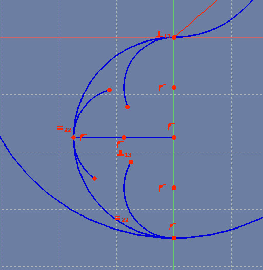
Now it’s time to constrain the Sketch to eliminate those 4 degrees of freedom:
- Constrain the upper endpoint of the lower arc to be coincident with the lower endpoint of the middle arc.
- Constrain the lower endpoint of the upper arc to be coincident with the upper endpoint of the middle arc.
Congratulations! You’ve created the basic Sketch of half of the duefoil. Remember that later on we’re going to fill in the other half, using one Polar Pattern Feature operation.
Thickening the Basic Design
Right now your half duefoil consists of infinitely-thin lines. Instead, you probably want a design that has some thickness, so it can be 3D printed, cut with a CNC machine, cut out with a scrollsaw, or painted onto a notebook cover. To thicken the duefoil, we’re going to create inner and outer arcs for every arc and circle in the original design.
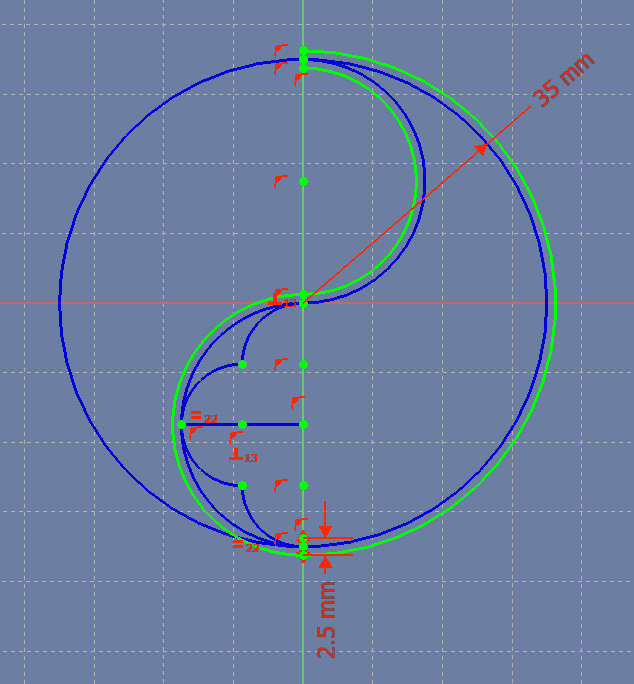
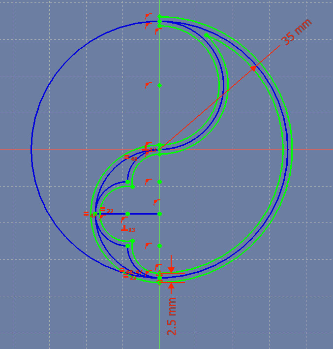
This work is a little more complicated, so it will help to first get a glimpse of what we’re going to create:
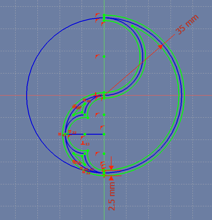
You may have noticed that in constructing the basic duefoil design, we used only one measurement: the 35 mm radius of the outer circle. That’s because the original Gothic designs were based on geometric construction that doesn’t use the markings on a ruler.
To keep to that goal, of using as few measurements as possible, next you’re going to create one little ruler to thicken the lines.
Create a short line anywhere near the bottom of the larger circle, then constrain it to be 2.5 mm long. We will use this line to eventually make every line and arc in our final duefoil 2.5 mm wide. If you want a thicker or thinner design, choose a larger or smaller length for this line.
Add a point at the center of this line: create a point, then add a symmetry constraint to make it half way between the line’s endpoints. That is, click one endpoint of the line, then the other, and finally the new point, then click the Symmetry Constraint icon.
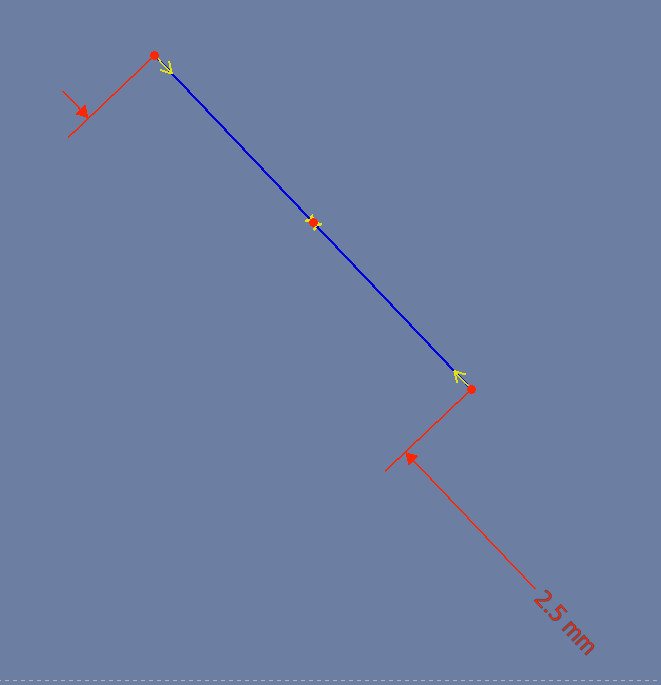
Now place the short line by adding the following constraints:
- Constrain the middle point of the line to be coincident with the point at the bottom of the large circle.
- Constrain one endpoint of the line to be fixed on the vertical center-line.
FreeCAD should once again say that our Sketch is fully constrained.
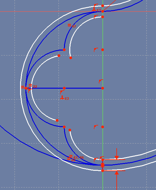
Now we’re going to start thickening the basic Sketch, starting with the outline of the whole design.
Switch from Construction Mode to Normal Mode, by clicking on that Construction/Normal icon. We do this because we’re going to be drawing the lines of the real object, rather than the construction lines of the basic design.
Create a large arc, then add the folowing constraints. This arc will be the outer edge of the whole design.
- Constrain the center of the arc to be coincident with the center of the large circle.
- Constrain the lower endpoint of the arc to be coincident with the lower end of the short line we created a moment ago.
- Constrain the upper endpoint of the arc to be fixed on the vertical center-line.
Once again our Sketch is fully constrained. Notice that the new arc, which started out white, has changed to green to show that the Sketch is fully constrained.
Create an arc, then add the following constraints:
- Constrain the center of the new arc to be coincident with the center of the lower semicircular arc.
- Constrain the lower endpoint of the new arc to be coincident with the lower end of the short line.
- Constrain the upper endpoint of the new arc to be fixed on the vertical center-line.
Continuing around the outline of the design, create another arc, then add the following constraints:
- Constrain the center of the new arc to be coincident with the center of the upper semicircular arc.
- Constrain the lower endpoint of the new arc to be coincident with the upper endpoint of our previous arc.
- Constrain the upper endpoint of the new arc to be fixed on the vertical center-line.
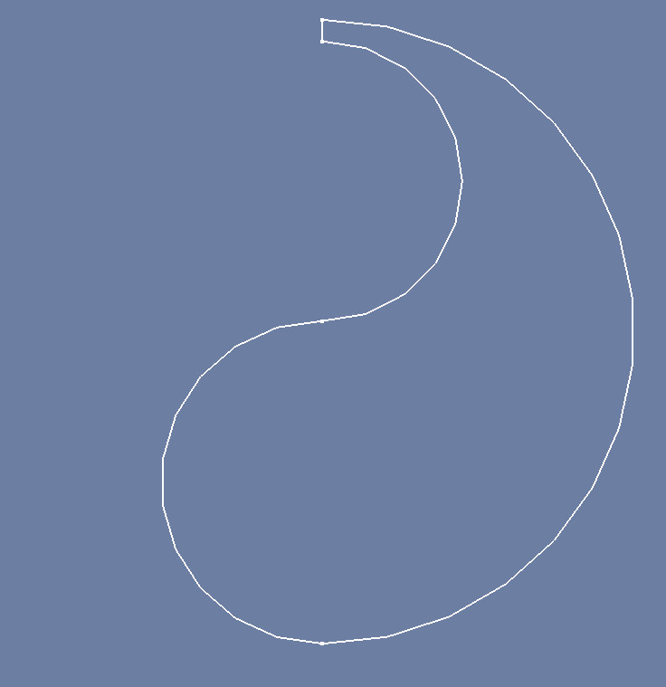
To complete the outline of the design, create a short line and make its endpoints coincident with the endpoints of the two arcs at the top of the figure (see the following image).
As a quick check, close the Sketch and save the file. In the Part Design workspace, the figure should look like the following image:
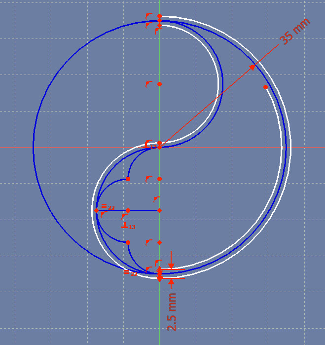
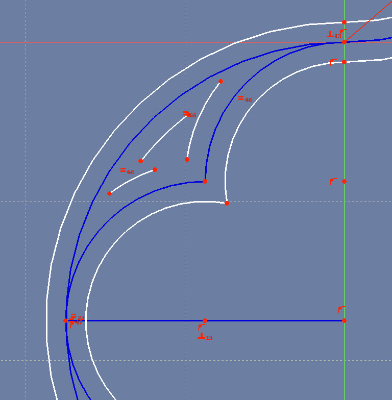
Now let’s create the inner outline of the design.
Open the Sketch, create a large arc, and add the following constraints:
- Constrain the center of the new arc to be coincident with the center of the large circle.
- Constrain the lower endpoint of the new arc to be coincident with the upper end of the lower short line.
- Leave the upper end of the new arc unconstrained for now.
Next, create three small arcs whose centers are coincident with the centers of the existing three small arcs.
Add the following constraints to the design:
- Constrain the lower endpoint of the lower arc to be coincident with the upper endpoint of the short line. That constraint will set the radius of the lower arc.
- Constrain the middle and upper arcs to be equal to (have the same radius as) the lower arc.
- Constrain the upper endpoint of the upper arc to be fixed on the vertical center-line.
Now connect the endpoints of the arcs:
- Constrain the lower endpoint of the upper arc to be coincident with the upper endpoint of the middle arc.
- Constrain the upper endpoint of the lower arc to the coincident with the lower endpoint of the middle arc.
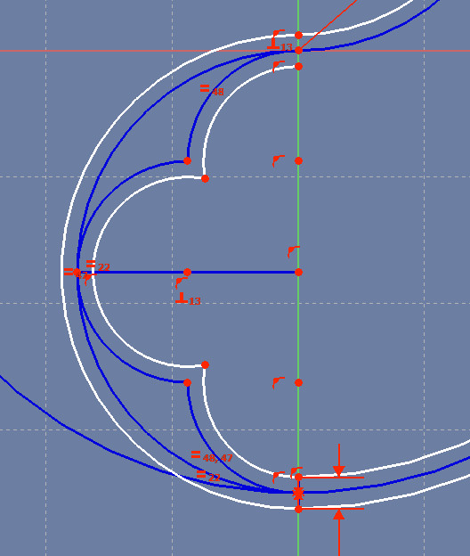
To complete the inner outline of the design, create a large arc in the upper part of the design and add the following constraints to it:
- Constrain the center of the new arc to be coincident with the center of the upper semicircular arc.
- Constrain the lower endpoint of the new arc to be coincident with the upper endpoint of the upper small arc – that is, coincident with the point just below the centerpoint of the large circle.
- Constrain the upper endpoint of the new arc to be coincident with the large arc’s endpoint that hasn’t been constrained yet.
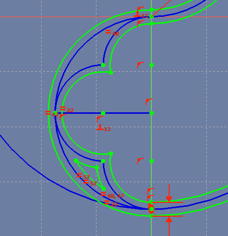
Notice that the Sketch has turned green, to show it’s now fully constrained.
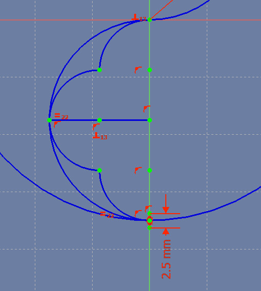
Next we’ll fill in the inner outlines of the two small, triangular spaces, starting with the lower triangular space.
Create an arc in the lower triangular space, and add the following constraints to it:
- Constrain the center of the new arc to be coincident with the center of the lower arc.
- Constrain the lower endpoint of our short line to be fixed on the arc. That is, constrain the new arc so that, if extended, it would go through the lower endpoint of the short line.
- Leave the two endpoints of this arc unconstrained for now.
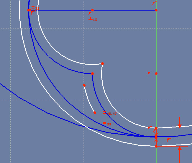
Create another arc in the lower triangular space, and add the following constraints to it:
- Constrain the center of the new arc to be coincident with the center of the middle arc.
- Constrain the new arc to be equal to (have the same radius as) the previous arc you created.
Create a third arc in the lower triangular space, and add the following constraints to it:
- Constrain the center of the new arc to be coincident with the center of the lower semicircular arc.
- Constrain the upper endpoint of the short line to be fixed on the new arc. That is, constrain the new arc so that, if extended, it would go through the upper endpoint of the short line.
Now simply connect the endpoints of these three arcs, completing the inner outline of the lower triangular space:
- Constrain the lower endpoint of the lower arc to be coincident with the lower endpoint of the middle arc.
- Constrain the upper endpoint of the lower arc to be coincident with the lower endpoint of the upper arc.
- Constrain the upper endpoint of the upper arc to be coincident with the upper endpoint of the middle arc.
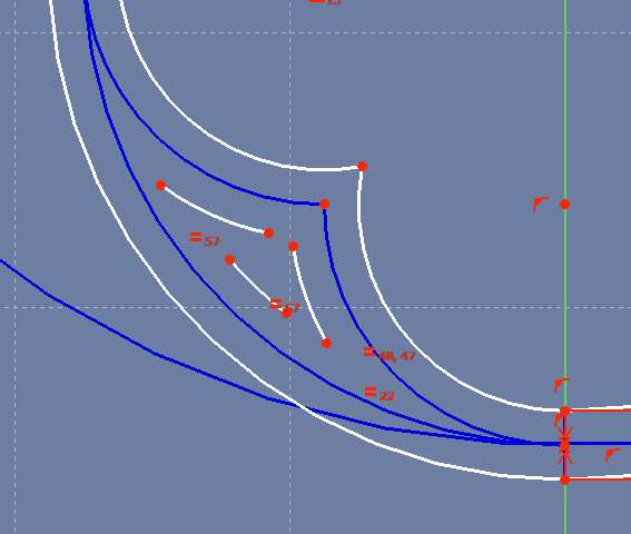
Now we’ll fill in the inner outline of the upper triangular space. Its constraints are a little different than those of the lower triangular space.
Create an arc in the upper triangular space and add the following constraints to it:
- Constrain the center of the new arc to be coincident with the center of the upper arc.
- Constrain the point that’s just above the center of the large circle to be fixed to the arc. That is, constrain the new arc so that, if extended, it would go through the point just above the center of the large circle.
- Leave the endpoints of this arc unconstrained for now.
Create another arc in the upper triangular space and add the following constraints to it:
- Constrain the center of the new arc to be coincident with the center of the middle arc.
- Constrain the new arc to be equal to the radius of the previous arc you created.
- Leave the endpoints of the new arc unconstrained for now.
Create a third arc in the upper triangular space and add the following constraints to it:
- Constrain the center of the new arc to be coincident with the center of the lower semicircular arc.
- Constrain the upper endpoint of the short line to be fixed on the new arc. That is, constrain the new arc so that, if extended, it would go through the upper endpoint of the short line.
- Leave the endpoints of the new arc unconstrained for now.
Now join the endpoints of these new arcs just as you did the endpoints of the arcs that are in the lower triangular space:
- Constrain the lower endpoint of the lower arc to be coincident with the lower endpoint of the middle arc.
- Constrain the upper endpoint of the lower arc to be coincident with the lower endpoint of the upper arc.
- Constrain the upper endpoint of the middle arc to be coincident with the upper endpoint of the upper arc.
The hard work is done! You’ve completed half of the duefoil.
Creating the Whole Duefoil from the Half
Next we’ll turn our 2D Sketch into a 3D half-duefoil, then duplicate that half to create the whole duefoil.
- Close the Sketch.
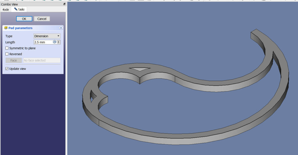
- In the Part Design Workbench, click the Pad icon.
- In the Pad Parameters tab, set the Length to 2.5 mm and click OK.
I chose a 2.5 mm Pad because my Sketch was 2.5 mm thick. A 2.5 mm pad makes the completed design have a square cross-section, which I like. If you instead plan to use the 3D duefoil to engrave a duefoil design on a box, you may want to choose a larger Pad Length.
Next, still in the Part Design Workbench, we’ll duplicate this half to make the whole duefoil:
- In the Model tab, click on (select) the Pad feature that created the 3D half duefoil. The padded half duefoil should turn light green to show it’s selected.
- Click the Polar Pattern icon in the toolbar.
- In the resultant PolarPattern Parameters window, set the Axis to Base Z Axis, the Angle to 360 degrees, and the Occurrences to 2 – that is, we want to make one copy (2 total) of the half duefoil, rotated in the Z axis, to fill a circle.
- Click OK
We have just one operation left to do. Because FreeCAD sometimes has trouble understanding overlapping 3D features, we need to “Refine” this Body to remove those overlaps:
- Switch to the Part Workbench
- In the Model tab, Click on (select) the Polar Pattern feature you created.
- Select the Part / Refine Shape menu item.
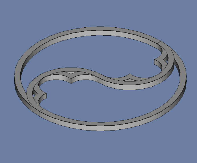
Notice that the resulting Body no longer has overlapping lines.
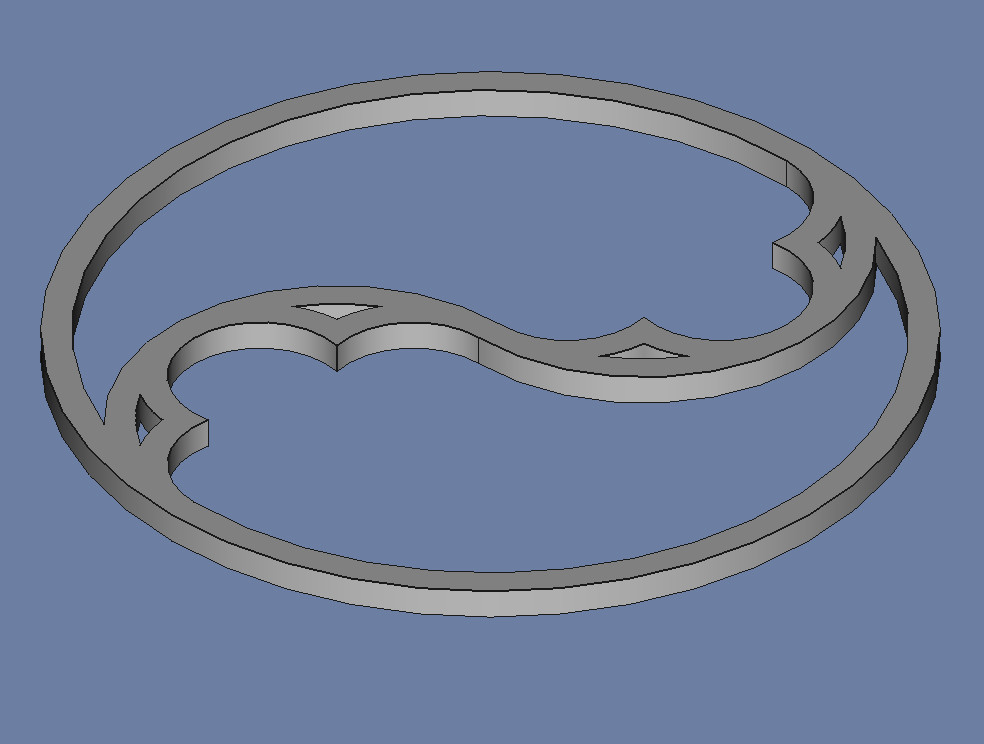
Your Gothic Duefoil is complete!