
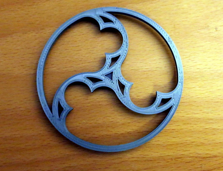
I’ve been interested in the Tracery in Gothic Cathedrals – the delicate patterns in stone walls and windows – for years. In this post, I show you how to design of one type of Gothic ornament, using FreeCAD. You can follow along with the FreeCAD file on Cults3D, or you can use your favorite CAD application, such as Autodesk Fusion 360.
Medieval architects used two tools for laying out designs like the Trefoil – a circle divided into three rings. The first was a straight-edge: a ruler, for drawing straight lines. The second was a compass – often called a pair of compasses: a simple device for drawing circles and arcs.
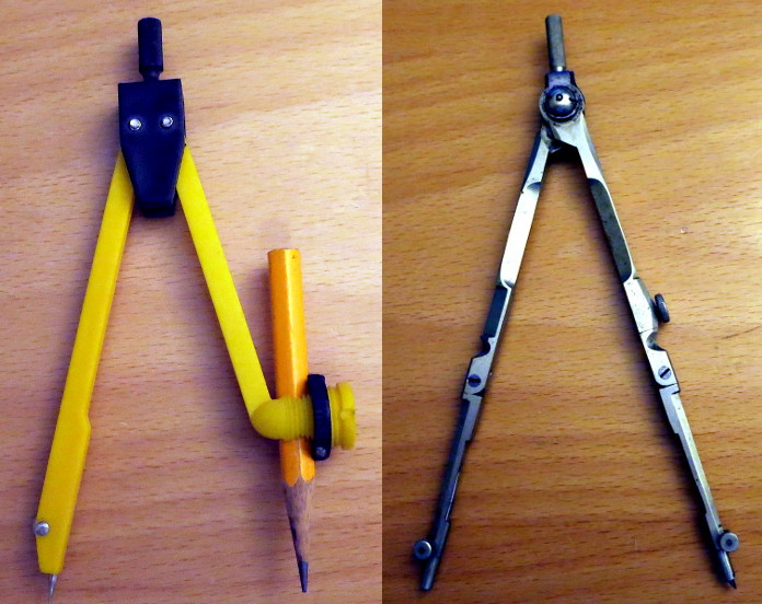
Until the appearance of CAD – computer aided design – programs, architects and engineers used these same two tools to draw everything from houses to airplanes. Even today teachers use these same tools to teach the basics of geometry.
I assume you’ve learned the basics of Geometric Construction with a compass and ruler, for example how to create a line perpendicular to another, how to bisect an angle, how to construct a circle tangent to two lines and touching a point, etc. You don’t have to know how to do these operations, but it will help you understand how the trefoil is constructed.
It begins with a circle
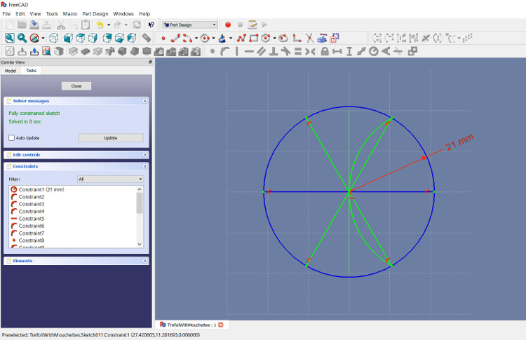
Start with a circle, centered on the origin (the center of the XY plane). Pick a size for your circle; I used a 21 mm radius. We want to keep our design from rotating, so put a horizontal line through the circle’s center, with each end touching the edge of the circle. These few Constraints should cause your CAD application to say this drawing is a Fully Constrained drawing, or one that has zero degrees of freedom. That is, there is only one circle and line that can satisfy the constraints you’ve created.
At each step, we want to finish with a Fully Constrained sketch, which tells you that your drawing is correct so far. It also makes the CAD application calculate less (run faster) as we go.
Once we have the circle and line, add an arc centered on the right end of the line and touching the center of the circle, with the arc’s ends touching the edge of the circle, as shown in the picture above.
Add two lines, from the ends of the arc, through the circle’s center, and to the opposite side of the circle. Notice, in the figure above, that now your circle is divided into 6 equal parts; your Geometry textbook can tell you why that’s true.
Next we’ll draw the first of 3 non-overlapping circles that fit into the larger circle. The first circle will be inscribed inside a triangle formed by two of the lines cutting the larger circle, and a line perpendicular to the line in between the two.
Construct a line whose right end is Tangent to (touches) the large circle. Add the constraint that the new line is perpendicular to the line that runs SouthWest to NorthEast. Make the left end of our new line touch the invisible line that our horizontal line is part of: in FreeCAD, click on the left endpoint of the line, click on the horizontal line, then click the “point meets an arc” icon (really “point meets a line” in this case.
Bisect the angle formed by that line and our original horizontal line. Create a circle centered on the intersection of that bisecting line and the SW-NE line through the center of the larger circle. Then make that new circle touch the point where your perpendicular line meets the smaller circle’s center line.
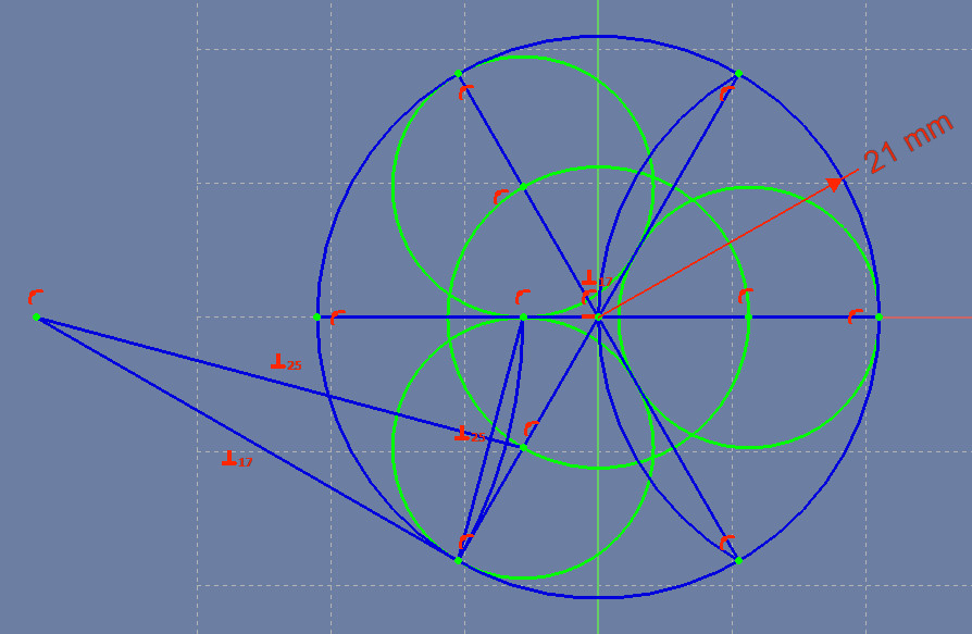
Next we’ll add the other two smaller circles, so we will have inscribed three touching circles inside the larger circle.
Create a circle centered on the larger circle and touching the center of the smaller circle we created a moment ago. Create two other circles, having their centers touch the mid-sized circle we just created, and their outside touch one of the two remaining lines that divide the circle. Have each of these two circles touch the largest circle as the point where their center line touches the circle. As a result of these constraints, these three circles are Tangent to (just touch) the outer circle and each of their neighboring circles. They’re also all the same size (again, Geometric Proof can tell you why).
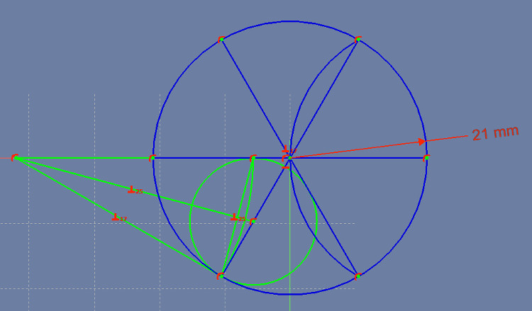
So far, I’ve shown you how to draw the figures using a compass and ruler, and it’s a lot of work. Fortunately, your CAD application can do a lot of the work for you: you simply tell it how the lines and arcs fit together, and it calculates where to put them.
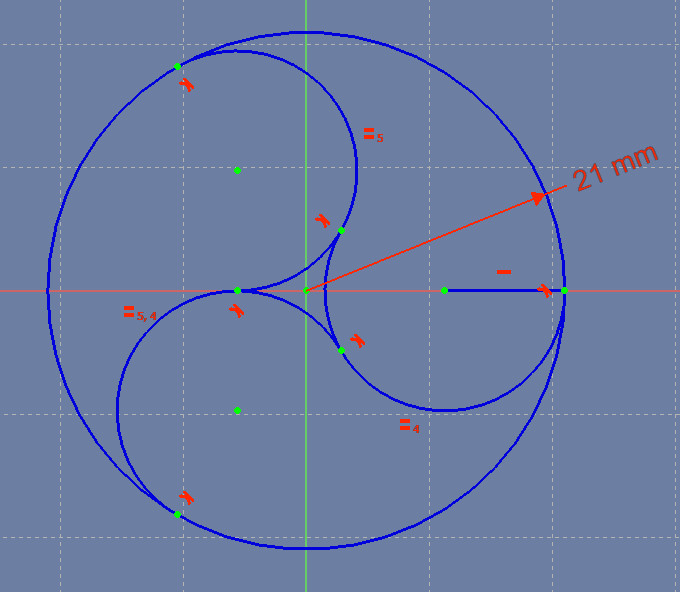
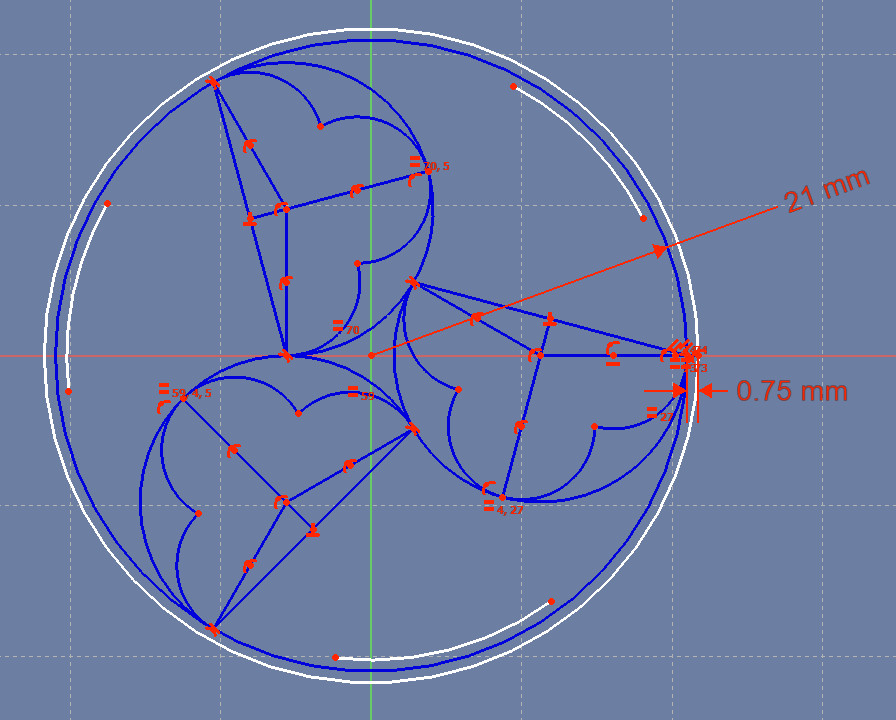
In the above figure we’re starting over, using constraints instead of mimicking drawing with the compass and ruler. As you see, we start with the same 21 mm radius circle centered on the XY origin, and a horizontal line touching the edge of that circle and invisibly going through the center of the circle, but we haven’t yet said where the left end of that line is.
Create an arc, near the right side of the circle, whose center is at the left end of the horizontal line (we still haven’t said exactly where that is). Make one end of the arc touch the right end of the horizontal line. We don’t care where the second end of the arc is yet.
Create a second arc, near the upper part of the large circle, Make one end of the arc tangent to the circle. That is, make the arc tangent to the circle at the endpoint of the arc.
Make the two arcs the same size (we don’t care what that size is just yet). Then make the first arc’s loose end touch the second arc, somewhere near the middle of that second arc (we don’t care exactly where yet).
Make a third arc, centered around the lower-right of the circle somewhere. Make one end of that arc tangent to the circle, like you did with the second arc. Make this arc the same size as the second arc.
Make the loose end of the third arc tangent to the first arc, somewhere near its middle.
Make the loose end of the second arc tangent to the third arc, somewhere near its middle.
Given those constraints, your CAD application should be able to come up with a solution that looks like the figure above, and it will say that your design so far is Fully Constrained.
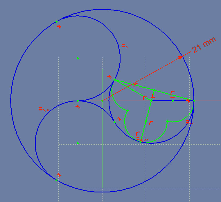
Next we’ll inscribe three equal-sized arcs inside the first of the three inscribed arcs.
First, create a line with one endpoint that touches the right end of the horizontal line, and whose other endpoint touches the point where this arc and its upper neighbor meet.
Notice that this new line forms the base line of an upside-down archway that’s a little larger than a semicircle. That type of arch is called a Rounded Horseshoe arch. We’re going to decorate that archway with three arcs, called Lobes.
Create a line that touches the left end of the line you just created, and whose other end touches the left end of the horizontal line (which is also the center of the arch we’re decorating).
Create a line whose end touches the center of the archway (the left end of the horizontal line), and whose other end touches the archway somewhere along its top.
Next, make the line you just created perpendicular to the base line of the archway. You should now have a fully-constrained drawing again.
Create the center arc of the three: make the center of the arc touch the perpendicular line you created. We don’t yet care where that center is along the line. Make the arc touch the end of the perpendicular line; that is, the top-center of the archway you’re working inside.
To set the size of the arc, constrain the circle your arc would make to touch the center of the archway we’re drawing inside. It’s a handy feature in FreeCAD: you just click that centerpoint and the arc and click the “point touches arc” icon. You’ll use this feature a lot to create invisible intersections of arcs and points.
We have now set the centerpoint and radius of the arc, but still haven’t said where the arc’s endpoints are. We’ll get to that later.
Create an arc whose center is on the horizontal line (again, we don’t yet care where on that line), and whose right end touches the right end of the horizontal line. Make the size of this new arc the same size as the arc you created a moment ago.
Constrain the left end of the arc to touch the right end of the arc you created a little bit ago. Be careful at this point: your CAD application can find two solutions to the intersecting endpoints problem, because there are two intersections of the circles that the arcs are made of. If it chooses the wrong intersection, the one that overlaps the two arcs, we’ll need to give it a hint: Undo, then move the two endpoints close to where you want them to meet, then click the “two points touch” icon.
Now just create the left arc, constrain its center, left endpoint, and radius in the same way you did the other one, then constrain its right endpoint to intersect the same way you did the other arc.
Now your drawing should once again be fully constrained, based on all the constraints you’ve added to the drawing.
Note: Sometimes FreeCAD (or any CAD application) will complain of an overconstrained arc, because you’ve explicitly set the radius, the center, and both endpoints, which makes four constraints instead of the minimum 3 constraints required. If that happens, change the end of the arc from intersecting a point to intersecting a line that contains the point. For example, you can change the right endpoint of the second arc from touching the right end of the horizontal line to simply intersecting the horizontal line at any point.
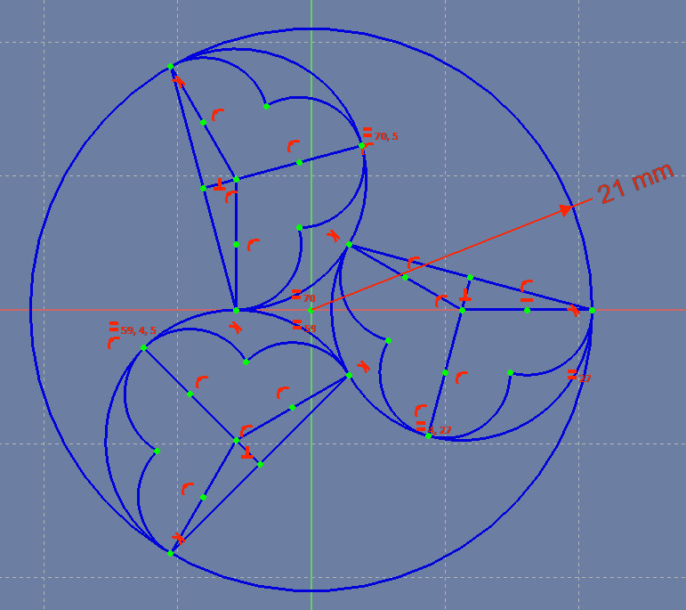
Repeat the process of creating those three smaller circles inside the remaining two archways. Congratulations! You’ve completed the geometry underlying the trefoil design.
The design so far isn’t ready to 3D print, because the lines have no thickness. Fusion 360 has a simple function to say “make all the lines in this Sketch 1.5 mm thick”. In FreeCAD we’ll need to draw all the edges of our 3D print by ourselves.
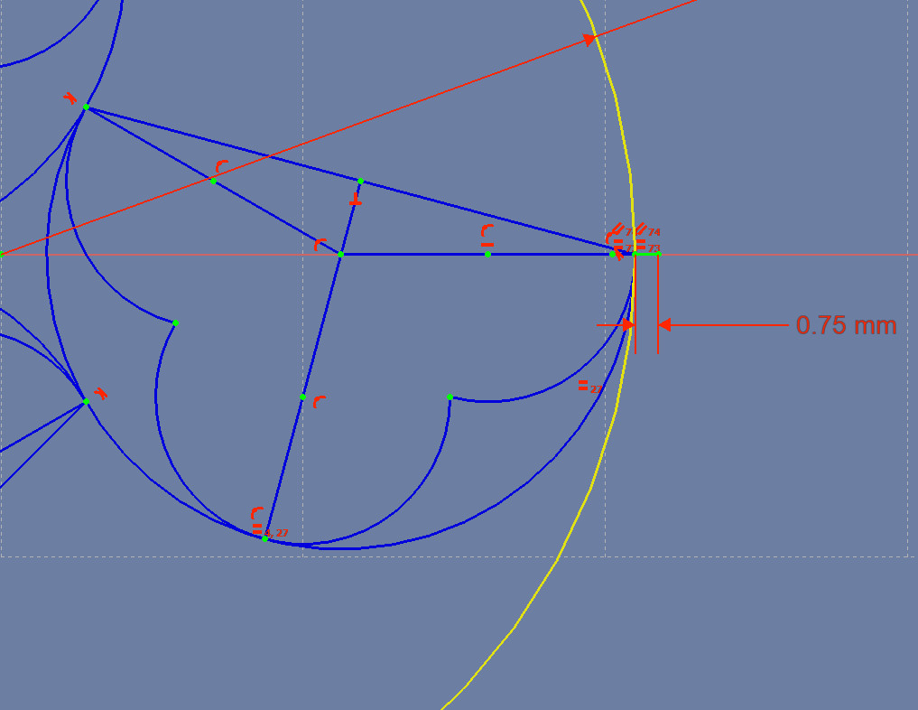
The first step in adding the edges is to set a constraint about the line thickness. Create a pair of connected lines, whose lengths are equal and that are parallel to each other. You now have a line with a marker point in its center.
Constrain the new line’s center point to touch the right end of the horizontal line, then constrain one end of the new line to touch the horizontal line (we don’t care where).
Set the length of the short, right line to be 0.75 mm long. Now you have two points that are 1.5 mm apart and are centered on the right end of the original horizontal line.
Next we’ll create the arcs that will be the edges of the outer circle of the figure: one circle will be a little larger than the original circle; a set of three arcs will be part of an invisible circle a little smaller than the original circle.
Create a circle with its center on the center of the largest circle. Constrain it to touch the right point of the small horizontal line you just created. That circle is the outside edge of the thickened large circle.
Create three arcs as shown in the figure above: make each arc’s center touch the center of the large circle. Make each arc’s invisible circle touch the left end of that short pair of lines you created recently. We don’t yet know where the endpoints of any of the arcs are, because they’ll be intersecting smaller or larger copies of other arcs in the figure.
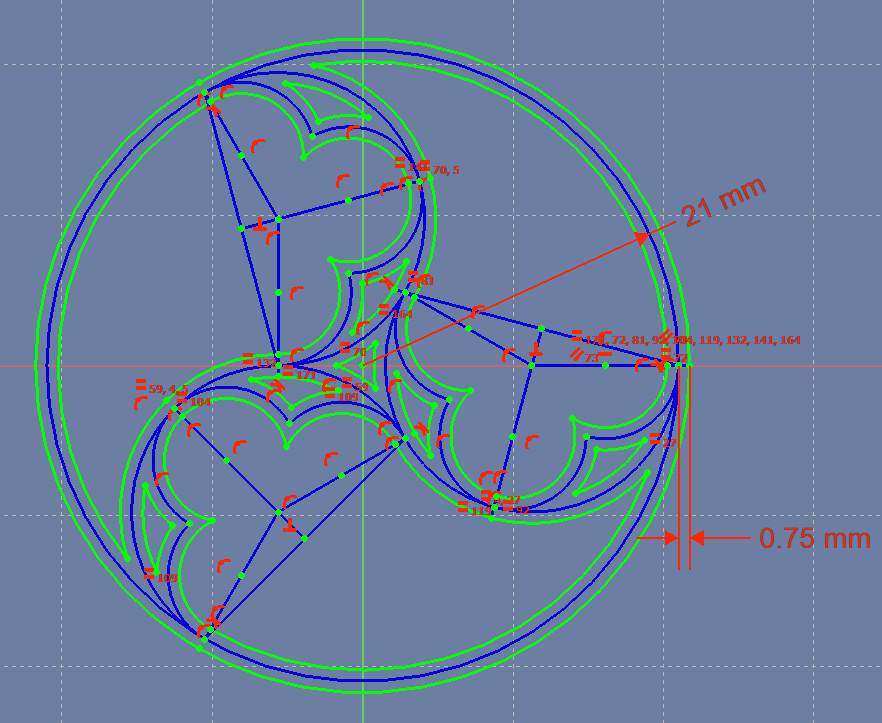
Use the same technique – creating points at the larger and smaller radii of an arc, then having the invisible circle intersect those points – to thicken all the other lines of the design. When you create other pairs of short lines, instead of re-stating the 0.75 mm length, simply make the short line length equal to that original short line.
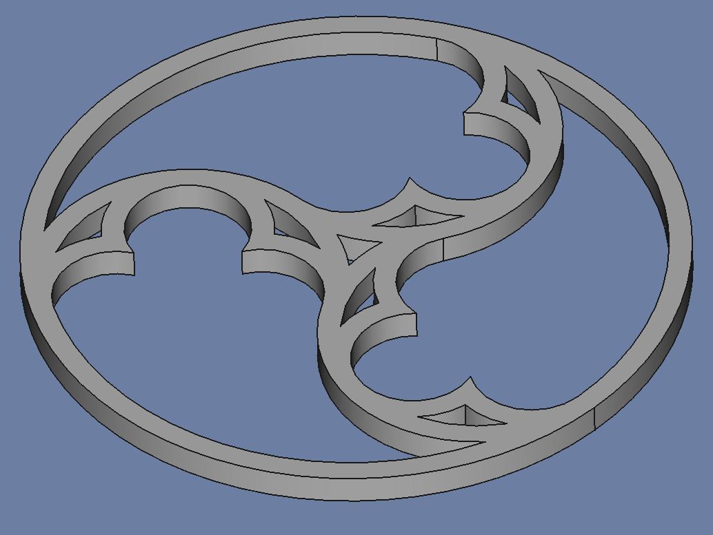
Your trefoil design is now complete! To turn this design into a 3D printable one, simple extrude (stretch in the Z direction) the Sketch by 2 mm, or whatever thickness looks good to you.
Because this design is constraints based, it’s easy to make the design bigger, by changing the 21 mm radius, or thinner, by changing the 0.75 mm thickness.
References
I’ve found it difficult to find references that go into all the details of the geometric construction of this figure. Because the audience of such references was usually a professional architect, highly skilled with compass and ruler, those references usually leave out many “obvious” details that aren’t so obvious today.

Meyer’s extensive Handbook of ornament contains a few sketches of gothic tracery, but without instruction in how to construct them. (tip of the hat to The Fullerine Incident).
Radford’s Cyclopedia of Construction, volume 2 (of 12) contains eight pages on how to construct a few examples of Gothic tracery. It leaves out several important details, but it’s the best description of constructing these figures I’ve found so far.