A few years ago at the Portland Oregon 3D printing Meetup, someone suggested we should all make our own name badges so Shashi wouldn’t need to bring as many “Hello, My Name Is” paper tags to the Meetups. A few weeks later I made a badge and a post on how to create your own, using the tools of the time.
This updated post walks you though the making of your own name badge in FreeCAD 0.21, which is a lot easier than it was in earlier versions of FreeCAD.
Tools and parts I Used:
- FreeCAD 0.21, a free and open source 3D CAD editor similar to Fusion 360, Sketchup, and Tinkercad.
- PrusaSlicer 2.7.1, a Slicer designed for the Prusa line of 3D printers.
- Prusa i3 MK3, a good 3D printer, that understands how to change filaments mid-print.
- Two contrasting colors of PLA filament for your printer. I used a PolyLite Red PLA for the background and PolyLite Yellow PLA for the lettering. I used PLA just because I like PLA. You don’t need a dual-extrusion printer.
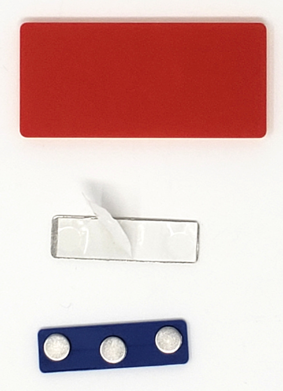
- Badge Magnets to fasten the badge to your clothes. Magnets don’t put holes in your clothes like badge pins do. (Thanks to Maz for this tip)
You can download my finished FreeCAD design file and STL file from Cults3D, Two-Color Name Badge.
Create the base and rim of the badge
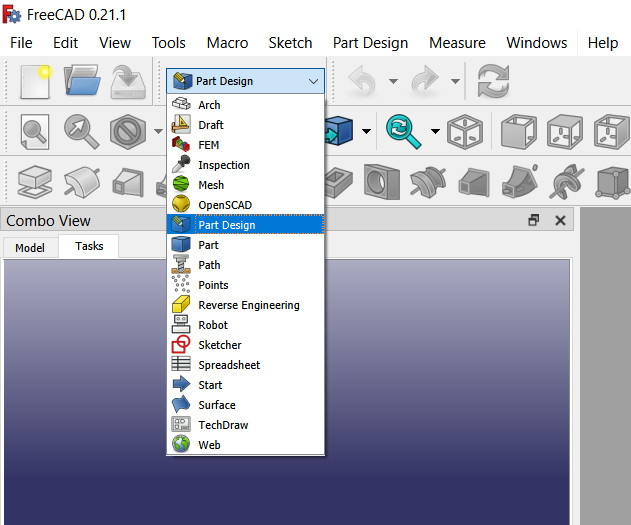
In FreeCAD, select the Part Design Workbench.
For brevity, I’ll gloss over some of the details of creating the base, because it involves FreeCAD operations you can easily learn from various online tutorials.
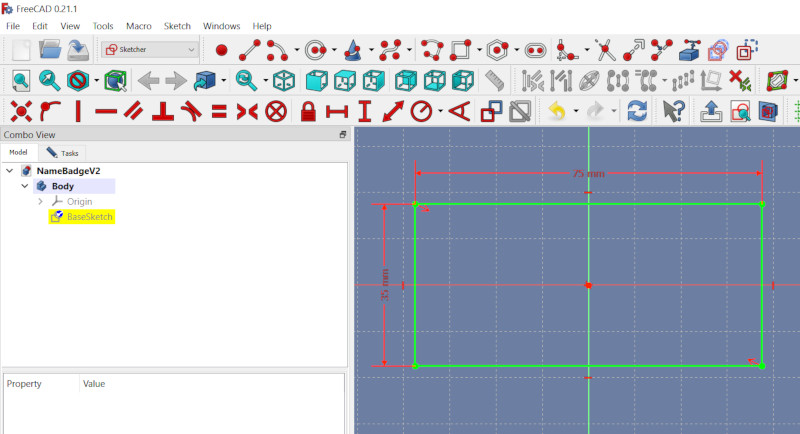
Create a FreeCAD XY-plane Sketch of a rectangle. This will become the base of the badge. I chose to create a badge 75 mm x 35 mm.
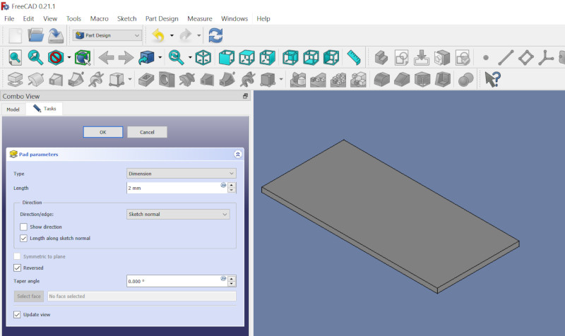
Extrude that base to the thickness you like for your badge. I chose 2 mm because that’s thick enough to be strong and thin enough to look nice. I also checked the Reverse option so that the lettering I add later will start at the top of the base. Click Ok.
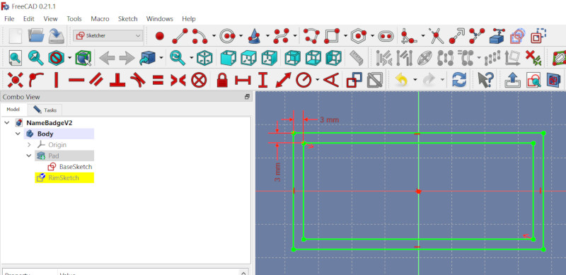
Next we’ll make the badge rim. I like a rim on the badge because it highlights your name and encloses the text of your name.
For the outside of the rim, create another Sketch in the X-Y plane, then use the Create External Geometry tool to reference the left and right lines of the Base Sketch you created earlier.
I chose to make the rim 3 mm wide because that’s about the thickness of the strokes in the text of my name.
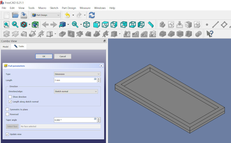
Extrude that rim to the same thickness as your planned name text. For example, I planned my name text to be 3 mm thick, so I extruded the rim 3 mm.
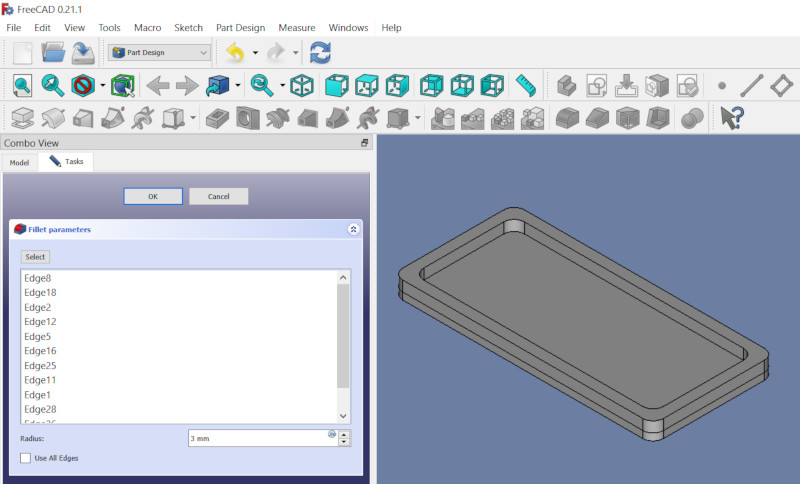
Next, round the outside and inside corners of the base and rim by selecting all the edges to round, then clicking the Fillet tool. I chose a 3 mm fillet to be similar to the thickness of the text.
Download a Suitable Font
FreeCAD ShapeStrings use font files rather than fonts that are installed on your system.
I prefer downloading fonts from Google Fonts because they’re open source (so I can use them in anything I like) and it’s easy to select fonts with particular attributes.
To download a Google Font:
- Browse to https://fonts.google.com/
- Select, for Decorative Stroke, Sans Serif, because small serifs don’t 3D print well.
- Under Sentence, type the text you want to use, so you can preview it in all the fonts.
- Click on a suitable font.
- Alternatively, you can type the name of the font you want in the Search Fonts bar. I like Open Sans. Then click on the font in the search result.
- Click Download Family.
- Extract (unzip) the downloaded .zip file.
- In the extracted folder, open the static sub-folder. FreeCAD requires static rather than variable fonts.
- In that static folder, copy the font file of the font that has the style you want. For this project I used an extra bold font: OpenSans-ExtraBold.ttf
- Paste that font file into your FreeCAD project folder. Do not install the font on your system.
Create your First Name
In earlier versions of FreeCAD, adding text involved a very cumbersome process of creating the text in Inkscape and importing into FreeCAD as an SVG image. Later versions of FreeCAD make the process a lot easier, although there are still a few tricks required.
We’ll add your name as two lines, each line of text being a ShapeString.
Orient the FreeCAD View of the badge so you’re looking down at the top (X-Y plane).
Select the Draft Workbench. It will take a little while to switch to this workbench.
Click on the Shape From Text (ShapeString) icon: the ‘S‘ icon.
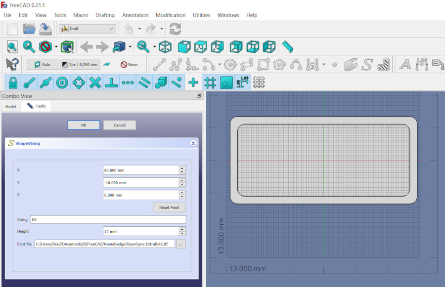
In the resulting dialog:
- Fill in the String field with the first line of your name (probably your First Name).
- For Height, select 12 mm. You will be able to adjust this font height later.
- For Font File, click the … button, then select the font file you recently downloaded.
- Finally, click the Reset Point button, then move the mouse directly to the OK button (without moving outside the dialog), and click OK.
Now the string will appear near the center of the badge Body.
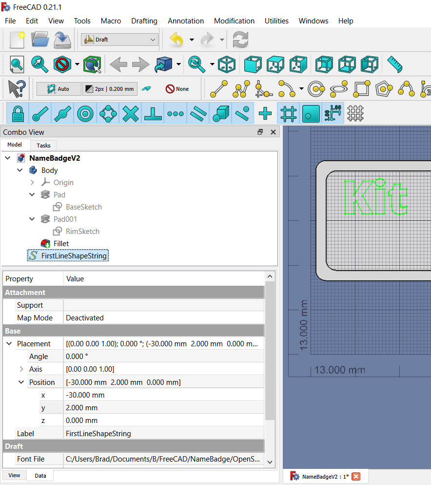
Next, use the Propery-Value panel to move the string to where you want it:
- In the Combo View (the tree view of the Body), click on the ShapeString that you just created.
- In the Property-View panel, under Base, expand Placement, then expand Position.
- Try different numbers for the X (left-right) and Y (up-down) values under Position to move the text relative to the badge. If you find the text hard to see, click in the Body’s pane to see the text, then click on the ShapeString in the Combo View to see the position again. There is no OK to click to finalize your position changes; they are immediately saved.
Attach Your First Name to the Badge
Right now the first name ShapeString is not part of the name badge FreeCAD Body. We need to add it to the Body:
- In FreeCAD, Select the PartDesign Workbench.
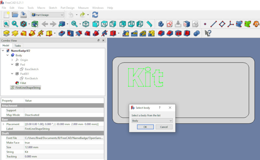
- Right-click on the ShapeString you just created and select Move object to other body.
- In the resultant dialog, select the Body of your badge (probably named Body).
- In the Property-Value panel,for Map Mode, click on the word Deactivated.
- Three dots (…) will appear to the right of the word Deactivated. Click on the three dots.
- In the resultant dialog, under Attachment Mode, select Object’s XY.
- Click OK.
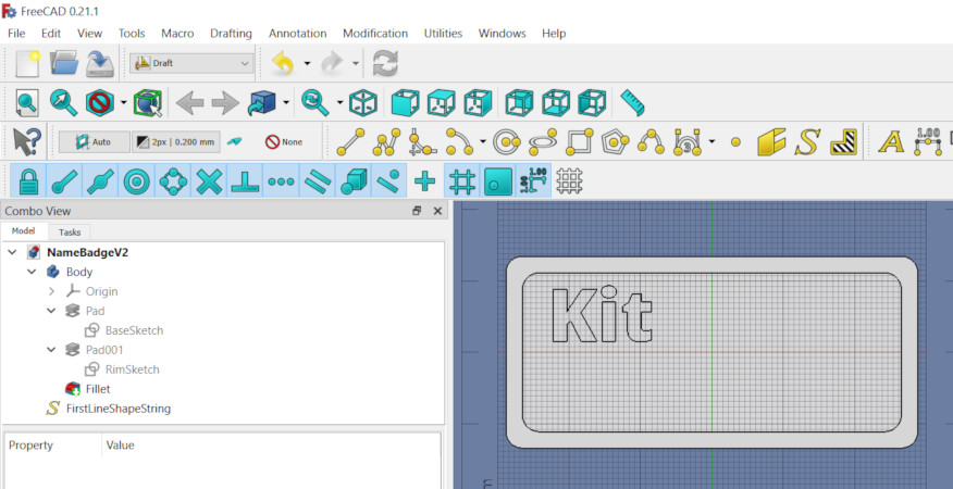
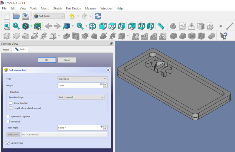
Now you can Extrude your first name, by clicking on the ShapeString you created, clicking on the Extrude icon, then, in the resulting dialog, choosing the text depth (3 mm) and clicking OK.
NOTE: if the extrude fails, the font you chose isn’t suitable for 3D printing; choose a different font (such as Google Fonts Open Sans).
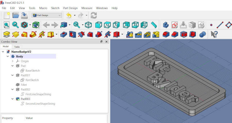
Create, Attach, and Extrude your last name
Repeat, for your last name, the process you used to make your first name: Create a new ShapeString using your last name as its text, position that ShapeString, attach that ShapeString to the badge Body, then Extrude that ShapeString.
Export for Printing
To export the STL file of this model:
- In FreeCAD, select the Part Workbench.
- Click on the badge Body
- Choose Part / Create a copy / Create simple copy
- Rename the copy to something sensible, such as “BadgeForPrinting”
- Click on the copy (BadgeForPrinting)
- Choose File / Export
- Name the exported file, something like “Badge.stl”
- Exit FreeCAD.
Slice the Badge STL File
PrusaSlicer and Prusa printers understand how to create multi-color prints by changing filament at a given layer. To tell PrusaSlicer to change filament color at the start of the lettering:
- Open PrusaSlicer and load your Badge.stl file.
- Click Slice now.
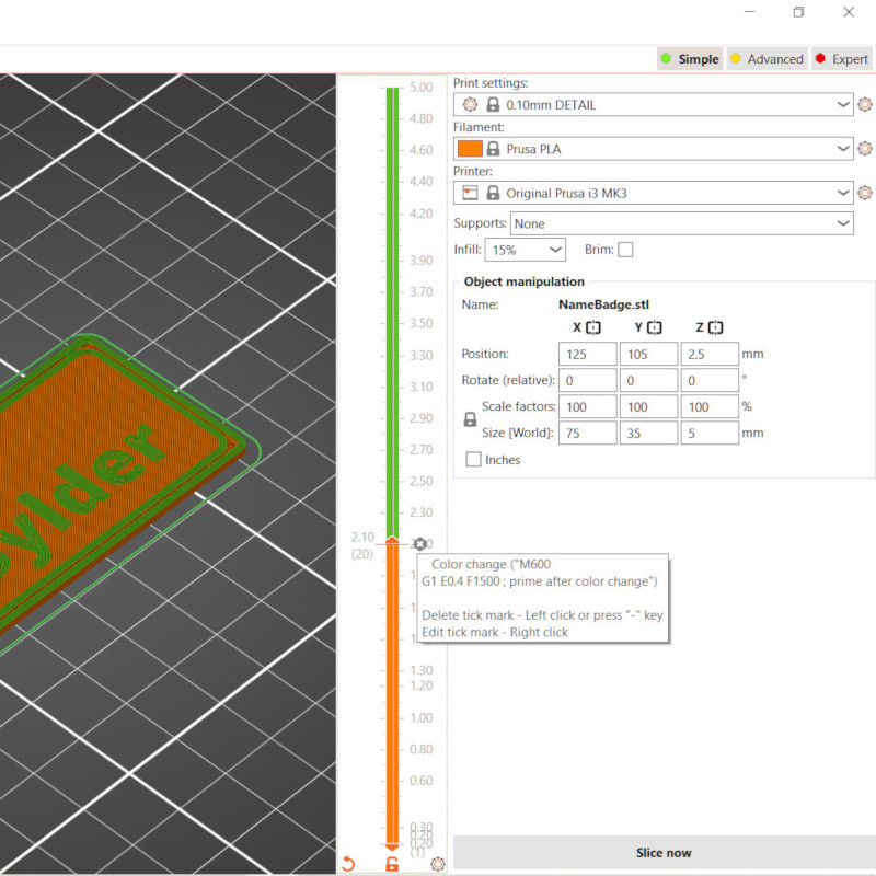
- Once PrusaSlicer is done with the initial slicing, a two-ended bar will appear to the right of the image of the print bed.
- Drag the top end of the bar down to the first layer of the text of your name (about 2.1 mm).
- Click the plus (+) sign that’s to the right of the end of the bar. Doing that will add a color change to the sliced output.
Continuing the slicing:
- Click Slice now once more.
- Once PrusaSlicer is finished slicing, click Export G-code.
- Save the resulting .gcode file somewhere.
Print the Badge
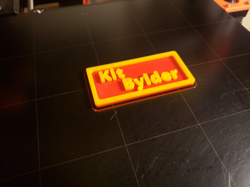
Load the .gcode file into your printer, load the background-color filament into your printer, and start the print. I used PolyLite Red PLA for the background color.
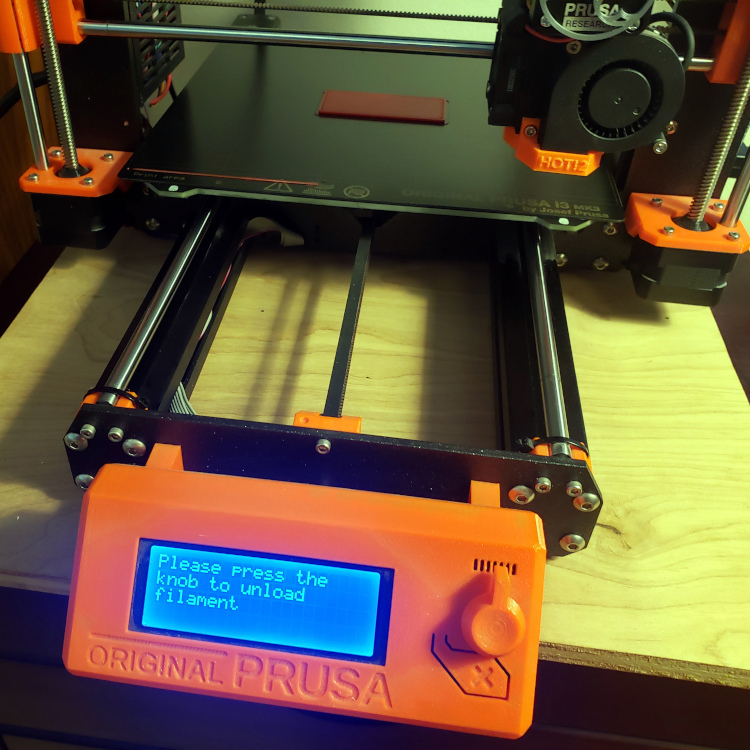
When the printer gets to the layer where the color changes (about 2.1 mm in), it will automatically pause and prompt you to unload the background-color filament and load the text-color filament. I used PolyLite Yellow PLA for the text color.
The printer will then continue the print, using the new color filament.
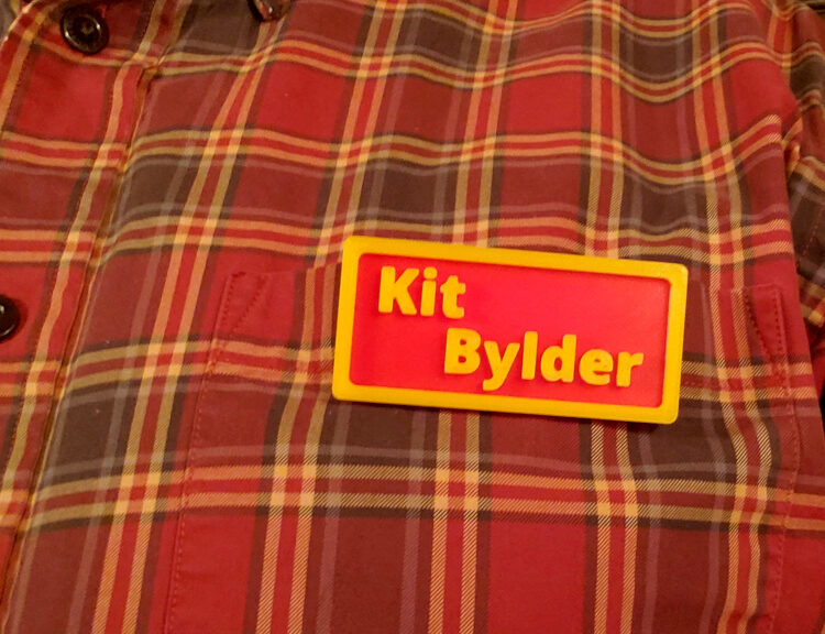
Once the print is finished, attach a badge magnet to the back of the badge.
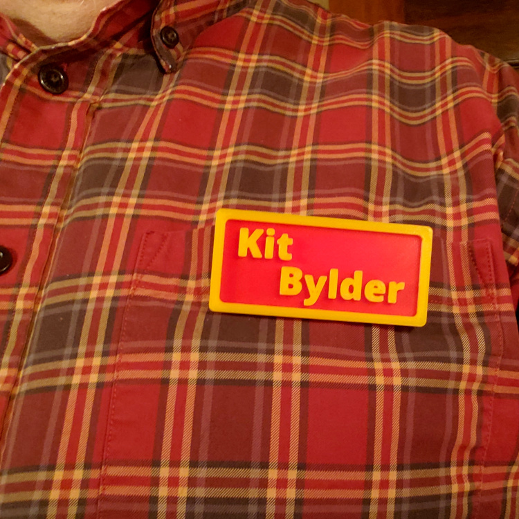
Your badge is now ready to wear – congratulations!
Trouleshooting
Some font files aren’t suitable for 3D printing, because the lines of the font cross each other.
To discover whether the font is good for printing:
- Open your finished badge design file in FreeCAD.
- Select the Part Workbench
- In the Combo View, select the copy you made of the Body (“BadgeForPrinting“).
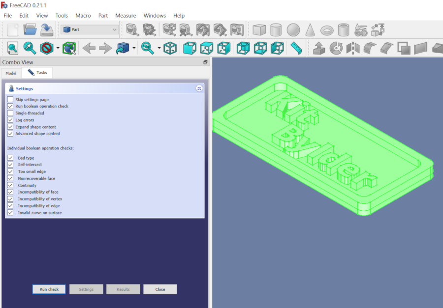
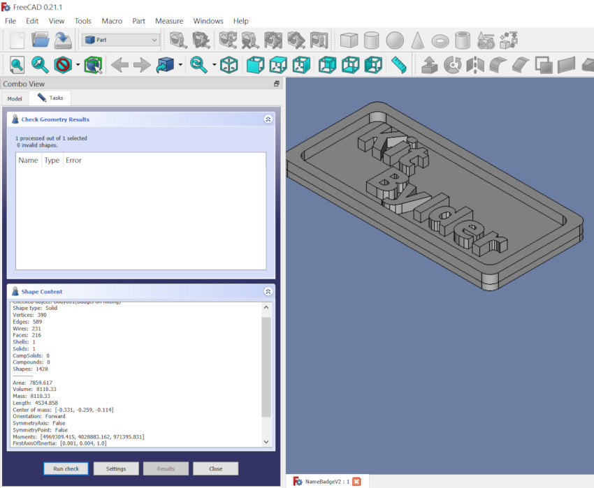
- Select Part / Check Geometry
- Click Run check.
If the font is suitable for printing, the check will show no errors.