The family cuckoo clock I’m working on is being capricious about when it decides to play the music, so I’ve built a test stand that will let me see what’s going wrong.
After looking through the wide variety of weight-driven clock test stands on NAWCC.org. I decided to build a floor-standing U-frame.
TL;DR: There are links to rough drawings of my completed plans at the end of this post, so you have something to start your own design from.
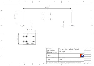
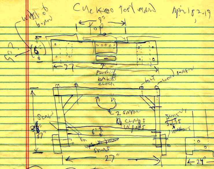
I started with a few quick sketches. I decided to make the frame the width of a fir or pine board – about 6 inches (about 150 mm), and to use angled parts and a cross brace turned on its side to reinforce the U structure. I also decided on wide feet to make the stand stable. The feet would also let me add leveling feet later if I need them.
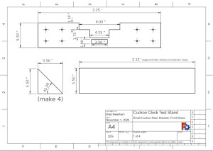
I also decided on a relatively elaborate cutout for the top, so the cuckoo clock would sit on the widest base possible, yet still have space for the surround (the front carving), the chains, and the pendulum. I also decided to make the top removable so I could make other tops to fit other clocks.
I designed the stand to use one standard size of board available where I live: 1 inch x 6 inches x 6 feet (about 25 mm x 150 mm x 1830 mm), though I wound up buying 1 x 6 x 8 foot boards because the lumber supply didn’t have 6 foot boards.
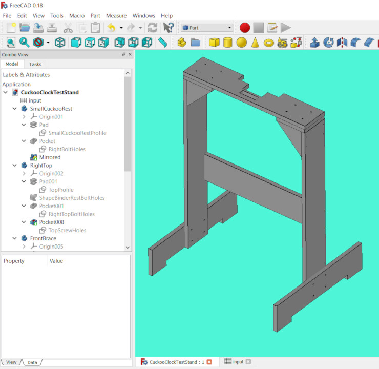
My rough guess was that the stand would need about 4 boards. For fun, I did the final design in Fusion 360. I recently recreated the design in FreeCAD, as part of moving all my designs from the proprietary Fusion 360 to the free and open source FreeCAD. You can see how several of the details changed as I filled out the design. For example, the angled boards for reinforcement turned into triangular pieces that would have more glued surface, making the frame stronger.
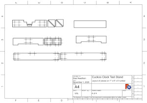
Once I’d finished the design, I created a flat pack layout to see how I’ll cut the parts out of the lumber: I simply made copies of all the pieces, oriented them all the same way, then laid the copies out on a model of my 1 x 6 x 6 board. This is still just a sketch: I haven’t allowed for the kerf (cutout) of the saw blade or the exact thickness of the board. A nominally 1 inch thick board is usually about 3/4 inch, but can still be plus or minus a 16th of an inch.

From the flat pack layout, I saw I needed only 3 boards, so I planned to buy 4 to be on the safe side. And as I said, once at the lumber yard I bought 8 foot boards instead of 6 foot boards. As you can see, everything is still a bit of a sketch.
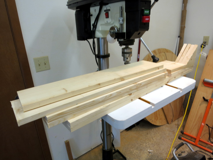
It was then quick work to measure and cut the pieces out using a miter saw. The one adjustment I made was to cut the lower brace piece to exactly fit between the legs, which depended on the exact thickness of the boards.
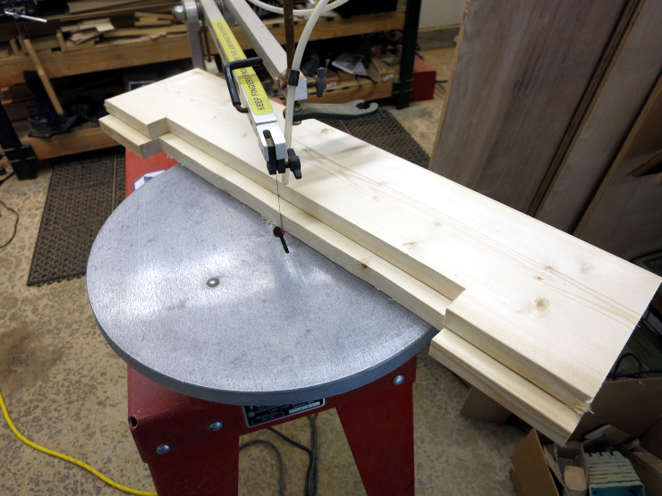
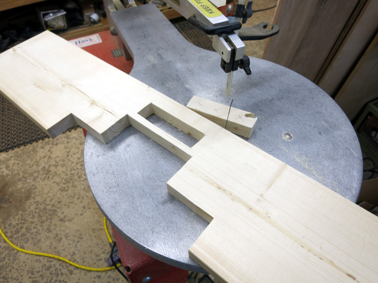
The next step was to use a scrollsaw to cut out parts of the feet and the top.
I hadn’t yet decided how to fasten the whole stand together. I knew I wanted to bolt the top onto the sides so that I could easily remove and replace the top, but beyond that I wasn’t sure. I had thought about using dowels and glue for a nice look, but decided that took more precision than I was up to at the moment.
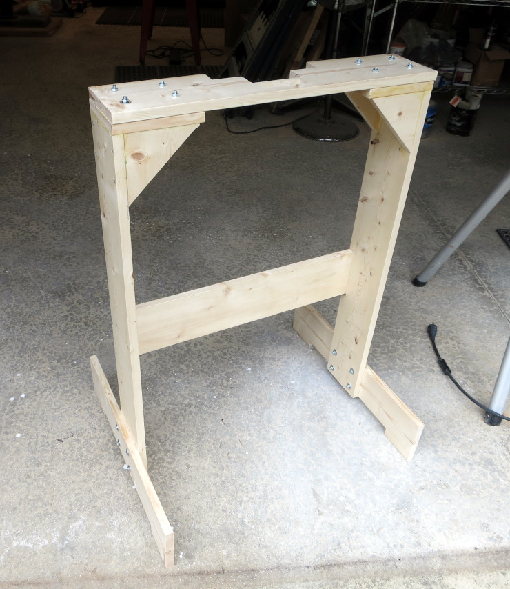
So I settled on using decking screws and glue to hold most of the frame together. It’s a bit rough looking, but that’s ok for this test stand. …oh, and the whole thing is way over-designed for the small weight a cuckoo clock will put on the stand.
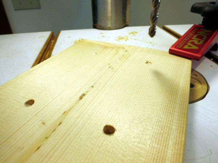
To make the frame easier to store I decided to bolt the feet to the legs rather than fastening them with screws and glue. To keep each foot aligned with its leg while drilling the holes, I pushed bolts into the existing holes as I went along.
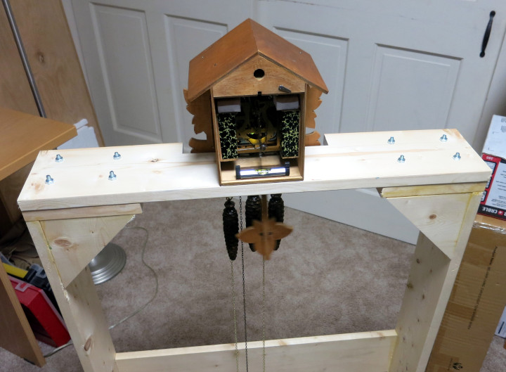
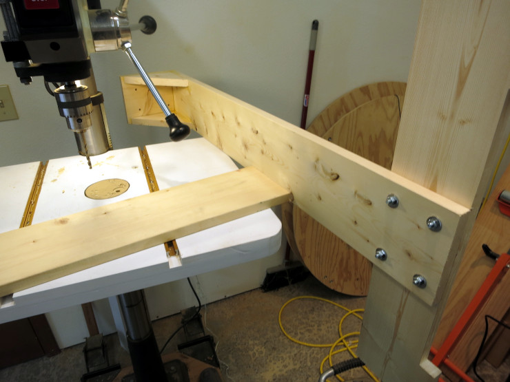
Then I fastened the cross brace. I put the brace against one side of the legs instead of the middle of the leg, so it wouldn’t get in the way of the cuckoo clock chains or weights.
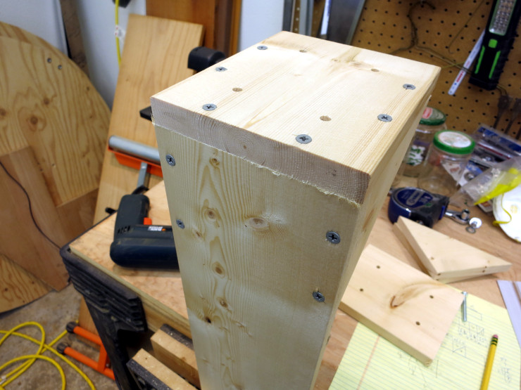
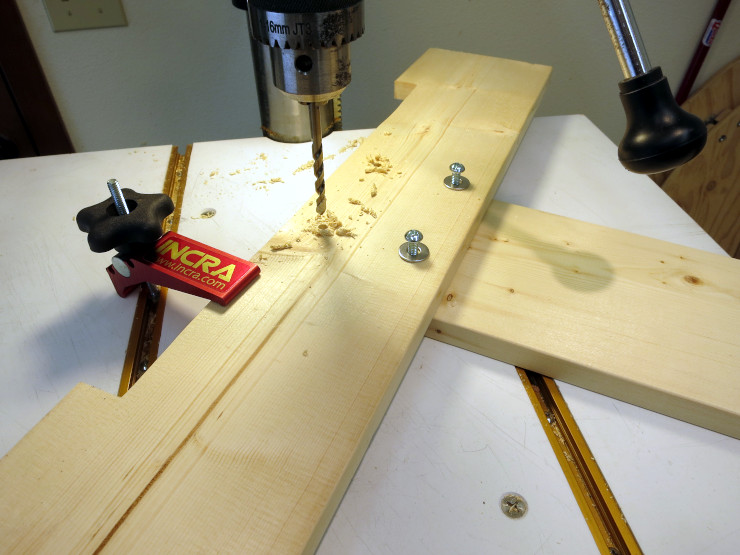
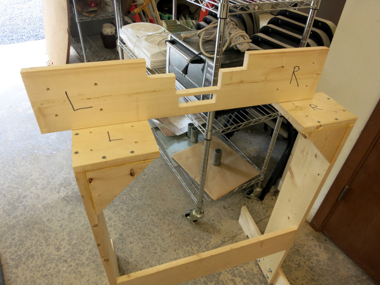
I then drilled the bolt holes in the top piece to match the existing bolt holes I’d drilled in the left and right top parts.
You can see from the photo that I didn’t have room to drill the outermost holes in the top. Instead, I fastened the inner bolts to align the top piece to the sides’ tops, then inserted bolts into the remaining holes and hit them with a hammer – that is, I used bolts as a sort of center punch to mark where to drill the outer holes. I then unfastened all the top bolts and drilled the final outer holes on the drill press.
Finally I marked the hidden faces of all the removable parts – the top and the feet – to align the correct bolt holes when I reassemble the frame.
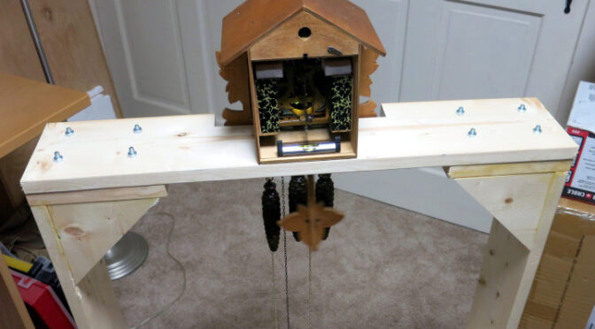
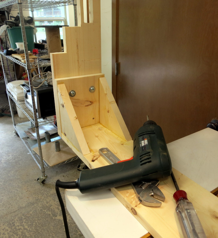
Being impatient, I’ve put the test frame to use right away to see what’s wrong with the music of the family cuckoo clock. Once I’m done, I have a short list of things to do to the frame: 1) spray it with a few coats of clear polyurethane finish, 2) replace the hexagonal nuts with wing nuts so I don’t need a wrench to assemble or disassemble the frame, and 3) add washers on each end of each bolt, to distribute the pressure of the bolt head and nut over a wider surface.
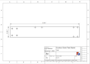
I haven’t included detailed plans here because you’ll want to create your own design to fit the size of lumber you buy, the size of your work area, and the type of clocks you want to test. I have included technical drawings (thanks to FreeCAD) of the pieces of my design, so you have something to modify to create your own design: