
In my previous post I finished cleaning my Goodwill clock, ending up with a jumble of gears and other parts. You may recall that when I disassembled this clock, parts sort of fell out willy-nilly, leaving me a bit fuzzy about what gears go where. In this post, I figure out which gears are part of the Going (time) Train (gear set), and as a bonus I calculate the length of pendulum this clock requires.
Finding which gears go where
It turns out that figuring out which gears are part of the Strike Train and which are part of the Going Train was a pretty straightforward process of identifying the gears unique to each Train, consulting the photos I took before disassembling the clock, and a little bit of trial and error.
TL;DR – I have a video showing the successful spinning of the going train gears: Testing the time gears on my first-ever clock repair.
A few parts of the Going (time) train were easy to identify:
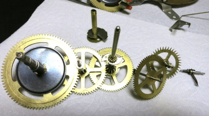
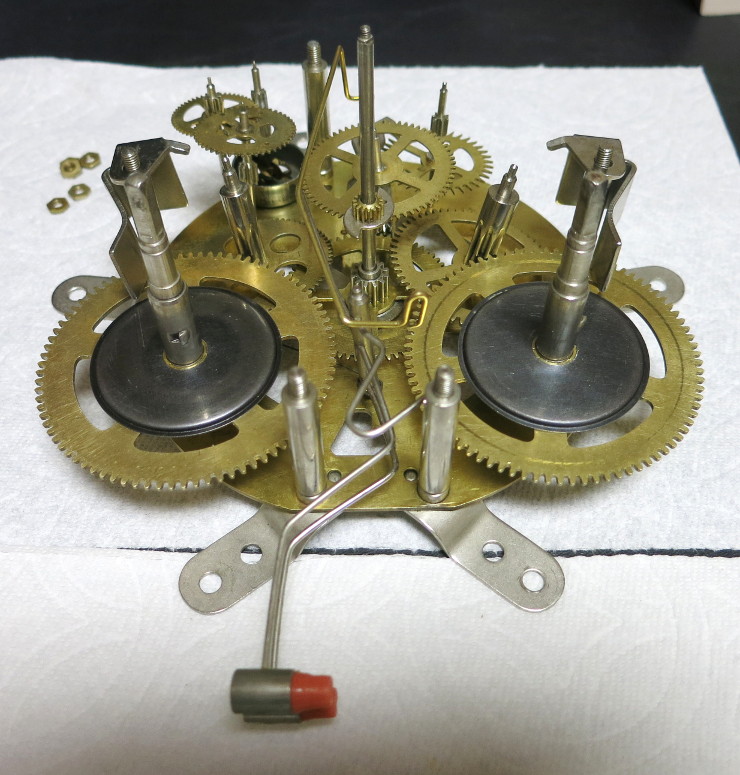
From my photos I could see that the Going (time) Great wheel (mainspring gear, upper left in the photo above, turned to see from behind) wound counterclockwise, compared to the one for the striking train. The Escape wheel (lower right) is easy to pick out because of its pointed teeth, that the Escapement ticks and tocks its way through. The Center wheel – that the minute hand attaches to – (upper right) has a a very long Arbor (shaft). In this clock, the hour gear (lower left) has the unique Snail (shell shaped gear) that controls the number of strikes that happen for each hour. The hour gear also has a hollow arbor that fits over the center wheel’s arbor.
Similarly, I could pick out a few gears that were clearly part of the Strike train:
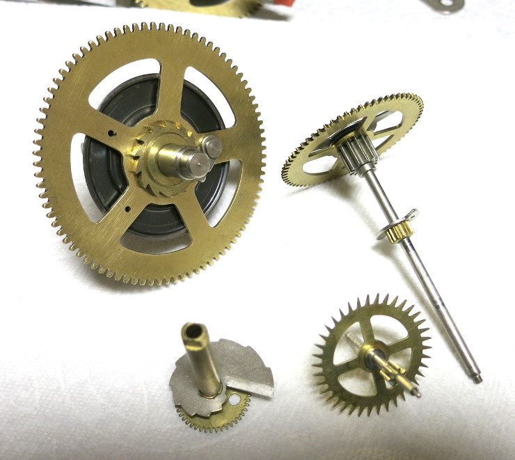
The strike great wheel (left in the photo above, seen from behind) is wound clockwise. In this clock, the Fan – the governor that controls the speed of the striking (far right) has a small pair of weights attached to springs. Another striking gear has a pin sticking out of it (lower center). I’m not sure exactly what that pin does yet, but I know the pin has to do with running the gongs. [Update: it’s the “Warning” pin, that starts the striking] Finally, I recognized the gear with the round holes in it (upper center) as part of the strike train in the photos I took before disassembling the clock.
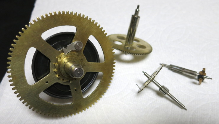
Once I’d separated the easily-identified gears, there were only a few gears remaining. I’m surprised how few gears a clock like this has.
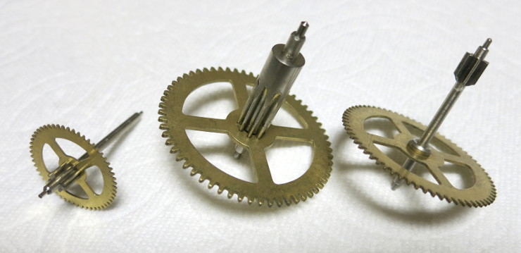
None of these gears were particularly easy to identify in the photos I had taken – oops, so I had to do a bit of trial and error by trying to assemble the gears into the back Plate of the clock and seeing what fit and seemed to mesh into which gears.
With only three unknown gears, it didn’t take long to find which gears fit where.
The missing pendulum
You may have noticed in the earlier pictures that a little stub is the only part of the pendulum this clock still has. I suspect the pendulum suspension spring finally broke off as the clock aged. …or maybe someone cut the pendulum off to sell as a separate part. I’m not sure. At any rate, this clock’s pendulum is missing.
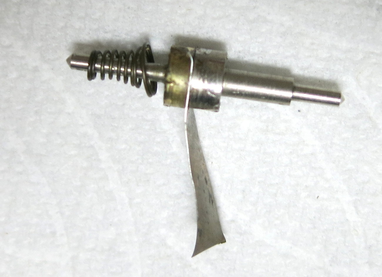
I’ve found a replacement suspension rod, and I suppose I can buy a Bob (pendulum weight) to fit it, but before I do that I want to know the length of the ideal pendulum: the distance from the pivoting top of the pendulum to the center of gravity of the total of the suspension rod and bob.
In truth, I went though all the calculations below before I found replacement parts, when I thought I’d have to make my own pendulum. Now they’re here mostly to show that math does work.
Counting the Teeth in the Going Train
The first step to calculating the pendulum length is to calculate the pendulum period – the time for a tick plus a tock – and to do that I needed to count the teeth in all the gears of the going train. Here are the results:
Great Wheel = no pinion leaves (pins), 84 teeth
2nd Wheel (that meshes with the Great Wheel) = 8 leaves, 60 teeth
Center Wheel (the minute hand wheel) = 12 leaves, 68 teeth
4th Wheel = 7 leaves, 66 teeth
Escape Wheel = 7 leaves, 38 teeth.
Additionally, the Center Wheel is the start of a small gear train that runs the hour hand:
Center Wheel = 15 leaves
Funky little wheel (I don’t know the name), driven by the center wheel = 40 teeth (would be pinion leaves), 10 teeth
Hour Wheel = 45 teeth.
Using Gear Ratios
From all those numbers, we can calculate the gear ratio – the number of turns a second wheel makes for each turn of a first wheel – based on the number of teeth and leaves in the two gears. For background information, see Working out Gear Ratios at TechnologyStudent.com.
For example, suppose we want to know how many turns of the center wheel are required to turn the hour wheel one turn. In other words, how many hours (full turns of the minute hand) are in 12 hours (a full turn of the hour hand)?
The funky little wheel turns 45 / 10 turns for every full turn of the hour wheel. Similarly, the center wheel turns 40 / 15 turns for every full turn of the funky little wheel. So the number of turns of the center wheel for every one turn of the hour wheel = 45 / 10 * 40 / 15, which comes out to 12. That is, the minute hand turns 12 revolutions (12 hours) for every one revolution of the hour hand (12 hours).
So, our gear ratio math seems to work.
Calculating the Period of the Pendulum
Now we can calculate the time per tick-tock of the clock:
The escape wheel has 38 teeth, and the escapement advances one tooth per tick-tock pair, so it takes 38 pendulum periods to turn the escape wheel one full turn.
One turn of the 4th wheel, which drives the escape wheel, takes 66 / 7 turns of the escape wheel. One turn of the center wheel takes 68 / 7 turns of the 4th wheel.
So the pendulum periods per full turn of the center wheel is 38 * 66 / 7 * 68 / 7, which is about 3480.49
The turn of the center wheel takes an hour, which is 60 minutes of 60 seconds each, so to convert our pendulum periods per center wheel turn into per second, we take 3480.49 / (60 * 60), which is about 0.966803 pendulum periods per second.
But we want seconds per period, so we calculate 1 / 0.966803, which is about 1.03434 seconds per pendulum period. I was puzzled why the clock designers picked this number instead of a round 1 second, until I found a hint on a thread about gear trains (since gone): “With an ‘integer ratio’, the same pairs of teeth (gear/pinion) always mesh on each revolution. With a non-integer ratio, each pass puts a different pair of teeth in mesh. (Some fractional ratios are also called a ‘hunting ratio’ because a given tooth ‘hunts’ [walks around] the other gear.)”
So it seems clock designers prefer non-whole-number gear ratios to even out the wear of the gears’ teeth. Who’d have guessed?
Calculating the Pendulum Length
The basic physics formula for an ideal (friction-less) pendulum’s period, given its length is: T = 2 * pi * sqrt(L / G), where T = the time of the pendulum’s period, in seconds; pi = 3.14159…; sqrt() represents the square root; L = the length of the pendulum, in meters because I like metric; and G = the acceleration due to gravity, which is about 9.8 meters / second / second.
That’s fine, but we want to know the ideal pendulum’s length given its period. That is, we need to solve the equation above for L, given T. Algebra comes to the rescue and produces: L = (T / (2 * Pi))^2 * G.
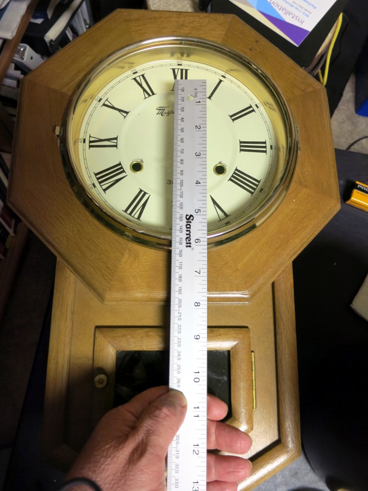
Given a period, T, of 1.03434 seconds, Pi of 3.14159…, and G of 9.8 meters per second squared produces a result of about 0.265579 meters. Millimeters are a little more convenient, so we multiply by 1,000 to get an ideal pendulum length of about 265.6 mm.
To roughly double check the math, I lined up a meter stick with roughly the suspension point of the pendulum and held my thumb by the 257 mm point on the stick: it roughly matches the middle of the window where this clock’s bob should be. So the math is in the neighborhood of correct!
Real vs. Ideal Pendulum Length
Here’s a head-scratcher: the replacement suspension rod (pendulum rod) for this clock is 12 inches long, which is 304.8 mm rather than 265.6 mm. Why?
The difference in length is because the suspension rod has weight, which makes the center of gravity of the rod + bob higher than the center of the bob. I’m assuming that the suspension rod is heavy enough, compared to the proper bob, that the center of gravity of the whole rod + bob is about 265.6 mm. I’ll know once I get the replacement parts in and get the clock running again.
Update: Now that I have the replacement suspension rod, I see that it’s deliberately as long as you could possibly need, and I’ll need to cut it to length and bend a hook in the end to hold the bob. To cut it to length, it will be useful to have the 265.6 mm estimate.
Later Update: I’ve learned that the theoretical pivot point of the pendulum is somewhere in the middle of the suspension spring, depending on the thickness of the spring, because that spring bends as the pendulum swings.
Calculating the Mainspring Turns per Month
This clock is advertised as a 30-day clock. That is, you need wind it only about once per month. How many turns of the winding key is that? That is, how many full revolutions of the going train great wheel happen in 30 days?
The center wheel (minute hand) rotates once per hour. The 2nd wheel turns 12 / 60 turns per turn of the center wheel. The great wheel turns 8 / 84 turns per turn of the 2nd wheel.
So for every hour, the great wheel turns 12 / 60 * 8 / 84, which is about 0.0190476 turns per hour. There are 12 hours per day and 30 days per winding, so we multiply by 12 * 30, which is about 6.89 – let’s say 7 – turns per 30 days.
So every 30 days, you should need to turn the winding key 7 full turns. I’ll be able to verify this number once I get the clock running.
In my next post, I buy new pendulum parts for this clock, to replace the missing ones.