
Today’s post is a How-To for a project I recently completed: a temperature-only Weather Underground Personal Weather Station made from an ESP8266, a MAX31820 temperature sensor, and a few miscellaneous parts. The whole project fits inside a 3D printed project box for mounting on an exterior wall that is sheltered from the weather.
The open source project files are in my MAX31820WeatherStation Github repository.
The project box
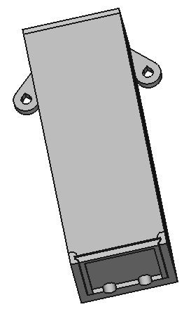
I designed the 3D printable project box, in FreeCAD, to keep the rain off of the circuit, to be easy to mount with nails to a wall, and to make it easy to pull the circuit out to see how it’s behaving. All of the design notes are in the diary file of the Github repository.
So the box I designed (also in the Github repository) has two nail holes for mounting, a sliding door at the bottom, and two holes at the bottom for the power cord and the sensor. You can’t see it in the above figure, but I angled the box so that when it’s mounted the top is sloped to keep the rain off.
The beauty of 3D printing is that to make your weather station project box, you just need to download the .STL files from the Github repository, and print them. I love 3D printing!
Soldering the Circuit
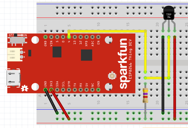
The circuit for the project is pretty simple, as you can see from the above Fritzing diagram. The MAX31820 temperature sensor is connected to power and ground, and its data line is pulled up to 3.3V with a 4.7K Ohm resistor.
Because it’s such a simple circuit, I decided to bare-solder the parts together, without a breadboard.
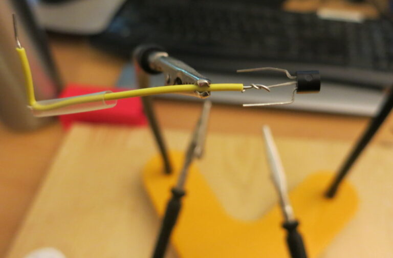
I first soldered power, data, and ground wires to the MAX31820 leads, using a simplified version of the Western Union splice.
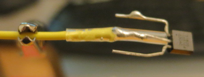
Once each leg was soldered, I slipped a little heat shrink tubing over the solder joint to protect it from the weather and to keep it from short-circuiting against the other MAX31820 pins. I then shrank the heat-shrink tubing with a heat gun.
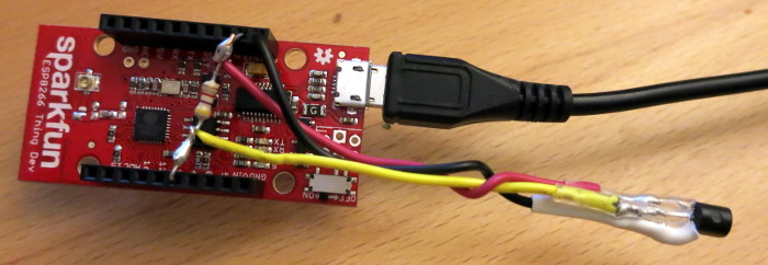
I then trimmed and bent the ends of the 4.7K Ohm pull-up resistor so that it would fit into the 3.3V pin socket and the data pin (pin 4) socket of the ESP8266.
I then removed the resistor and soldered the yellow MAX31820 data wire to the data side and the red power wire to the power side. The circuit is complete!
Reading your sensor’s 1-Wire Address
The MAX31820 temperature sensor runs on a 1-wire bus. Each temperature sensor has a unique address on that bus. That address is sort of like a serial number; a different address is built into each sensor when it is manufactured.
Our Arduino Sketch includes the 1-wire address of the MAX31820 in the circuit. You’ll want to replace the address in the current Sketch with the address of your particular sensor.
- Open the Arduino Sketch.
- Find #define PRINT_1_WIRE_ADDRESS true in the Sketch, and uncomment that line.
- Run the Sketch. Look at the output in the Arduino Serial Monitor. That output is the address of the MAX31820 temperature sensor in your circuit.
- Copy the address the Sketch printed out.
- Re-comment-out the #define PRINT_1_WIRE… line.
- Find the line reading DeviceAddress sensorAddress = …
- In that line, replace the sensor address with the address the Sketch printed out.
Registering the new Weather Station
The Readme.md file in the Github repository explains how to register your new Personal Weather Station with Weather Underground. Basically you create an account on Weather Underground, then follow the instructions.
If you’re interested in privacy, be aware that you’ll need to tell Weather Underground – and everyone who sees data from your weather station – the latitude and longitude of your station. That’s probably your home address. So if you don’t want to share your home address with whoever, you may want to be coy about who that new station belongs to.
Once you’ve finished registering the station, Weather Underground will show you a Station ID and Station Key for your weather station. Write this ID and Key in a safe place, because you’ll need it to program your station.
Coding the SSL Certificate’s Fingerprint
Weather Underground is an HTTPS site rather than HTTP, and the ESP8266 HTTPS stack requires the SSL Fingerprint for the site it is to reach.
The good news is that as of this writing, the current Weather Underground SSL Certificate Fingerprint is already in the Arduino Sketch.
Once Weather Underground’s current SSL Certificate has expired and been replaced with a new one, you’ll need to add the new SSL Certificate’s Fingerprint to the Sketch. Just follow the instructions in the Arduino Sketch to visit Weather Underground, examine its SSL Certificate, download that Certificate, and use OpenSSL to extract the Fingerprint.
Note: If you use Windows, the git bash command puts you in a command-line environment that includes Open SSL so all you have to do is install git to be able to use Open SSL.
Loading the EEPROM
To avoid having WiFi and weather station credentials in the git-maintained Arduino source, the Sketch reads those items from the ESP8266 EEPROM. You’ll want to program your ESP8266’s EEPROM with your WiFi hotspot credentials and Station credentials.
Begin by choosing what WiFi hotspot your weather station will connect to. Write down the SSID and password for that hotspot.
Follow the instructions in the Arduino Sketch (MAX31820WeatherStation.ino in the Github repo) to program the EEPROM using my write-eeprom-strings Arduino Sketch, in my write_eeprom_strings Github repository.
Once you’ve programmed the EEPROM, program the ESP8266 with the weather station Sketch, MAX31820WeatherStation.ino.
Mounting the project box
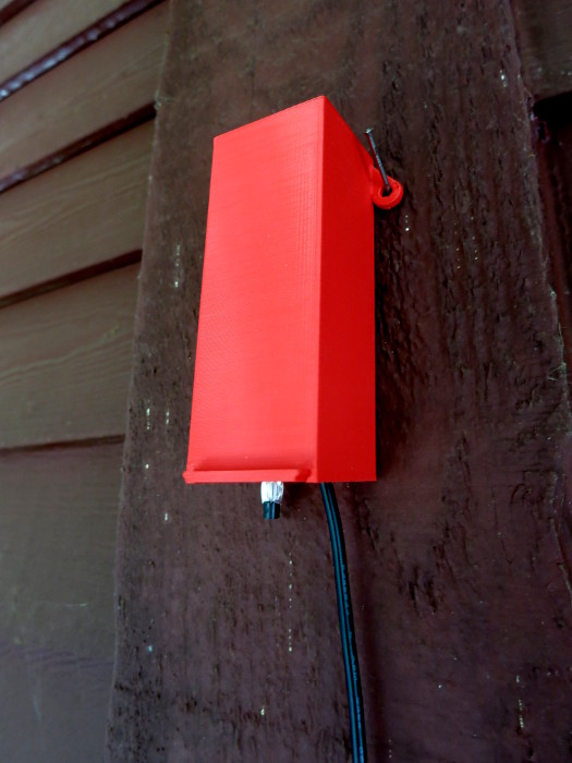
Pick an external wall, sheltered from direct sunlight and the rain, and near an outdoor power outlet. Drive two nails into that wall and hang the weather station as shown in the photo above.
Notice that the temperature sensor is outside the project box, so it’s not affected by the heat generated by the ESP8266.
View your new Weather Station’s data
After about 1/2 hour, login to Weather Underground, select your personal weather station, and click on its ID to see its data. You’ll probably want to bookmark this data page so you can see the temperature at your house regardless of where you are.
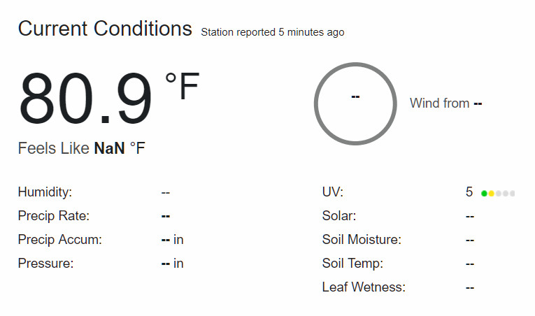
As you can see from the screen shot above, my station is uploading the temperature!
If you are interested in expanding your weather station to include humidity, See the DHT22 Temperature and Humidity sensor. Note: that sensor uses 5V data and power, so you’ll need a 5V power supply (the unregulated Vin for the ESP8266 should work) and a 3.3V/5V level converter to use that part.
If you want to build a nicer weather station, search “DIY Weather Station” to find parts and instructions for inspiration. The Weather Underground PWS protocol supports very rich and complex weather data, so the Arduino Sketch changes you’ll want to make will be small.
Enjoy the hot days of Summer! …or the cold days of Winter if you’re in Australia or other spots South.