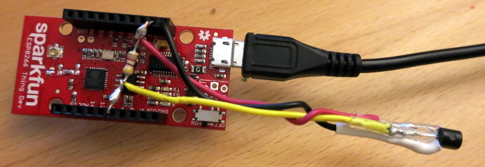
Today’s post is a How-To for a project I recently completed: a temperature-only Weather Underground Personal Weather Station made from an ESP8266, a MAX31820 temperature sensor, and a few miscellaneous parts. The whole project fits inside a 3D printed project box for mounting on an exterior wall that is sheltered from the weather.
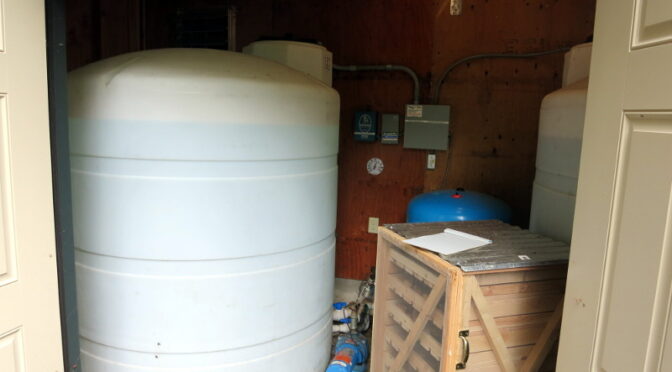
In my previous post I started the electronics and software for an Arduino Sketch for an ESP8266 WiFi microprocessor and several MAX31820 temperature sensors, that will eventually estimate and upload the level of water in our well water tank.
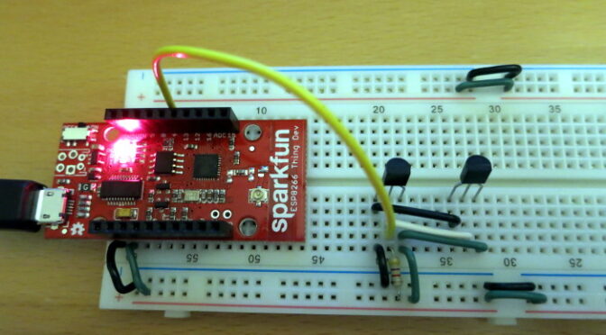
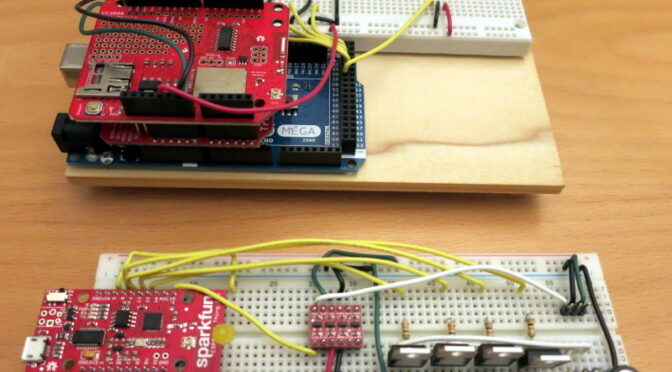
Since my last post I’ve updated the WellDepthTemperature github repo for the project to read 12 temperature sensors and to do a better job of reporting WiFi errors. That code now successfully identifies and reads the temperature from 12 MAX31820 sensors via a Sparkfun ESP8266 Thing Dev board, all on a breadboard for now.
I’ve begun another Arduino/ESP8266 project: reporting the level of water in our well tank. This project will involve the ESP8266, MAX31820 temperature sensors, some mechanical work, sending data to a web-based database, and interpreting the temperature data to estimate the well water level.
I have to confess that sometimes I need a push to make the right design choice.
It’s been a long time – way too long – since I worked on my Lunar Clock project. In the meantime, Sparkfun has introduced new, inexpensive microcontrollers aimed at Internet-of-Things applications. I knew one of those new microcontrollers would be perfect for the Lunar Clock, but I dragged my feet.
Then one day, a Github user pointed out that one of the boards I was using has been obsoleted.
For some time we’ve caught rare glimpses of small, rabbit-like animals who seem to be living under our front porch. We’ve seen little, round ears bobbing past the window, footprints in the snow, and during one hot summer I found a dead chinchilla in the garage – the poor thing couldn’t take the heat.
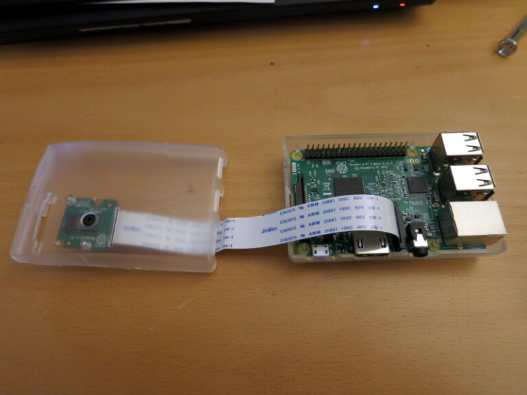
So I’ve decided to capture photos of the little fellows – or at least try – using a Raspberry Pi, motion-detecting Webcam. The project as it unfolds is stored on my ChinchillaCam Repository on github.
Now that my Dog Bed Weight Scale is sending data, I’m going to have a go at a water bowl scale. The idea is that, like the bed, the bowl will periodically send its weight to a cloud. This data should tell me when Pippa drinks, when we refill her bowl, and (maybe) how much she drinks.
The work-in-progress sources on Github, contain the beginnings of the Arduino 101 Sketch, Bill of Materials (Parts List), mechanical design/construction details, and a day-by-day project diary.
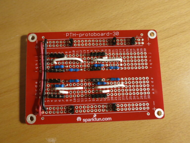
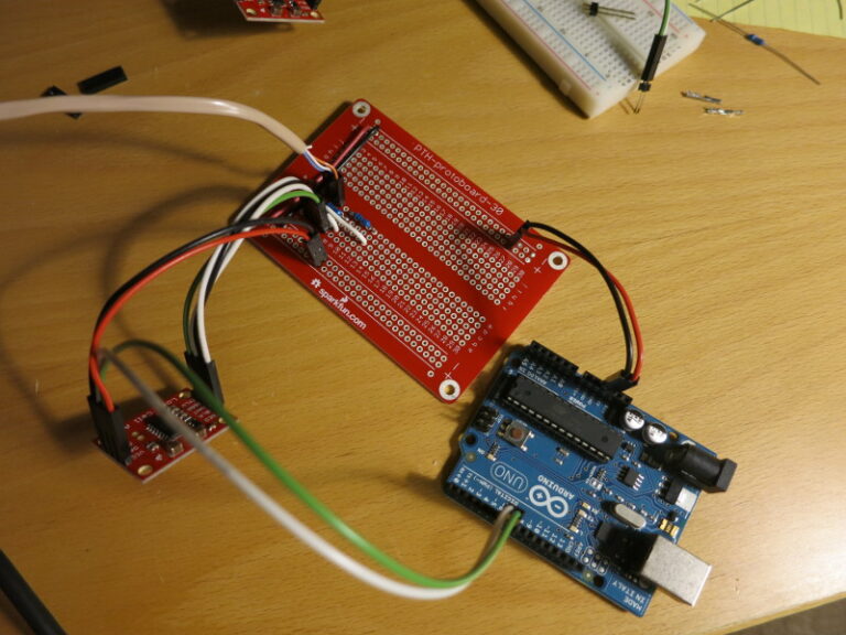
In my previous post I described how to use long break-away headers, and started soldering the circuit together. In this post I finish transferring the scale circuit from the breadboard to a protoboard, and do a quick test mount of the circuit on the plywood scale base.
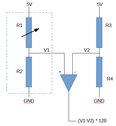
A reminder: I found that the Load Cell Amplifier was (by design) so sensitive to changes in resistance that just touching the resistors on my solderless breadboard caused large changes in the Amplifier output. So I wanted to solder all the parts down.
It’s a good time to recap: This project is a scale that will sit underneath my dog Pippa’s bed, so that I can measure her weight automatically, at night while she sleeps. The project-in-progress is Open Source, at my CurieBLEWeightMonitor Github repository.
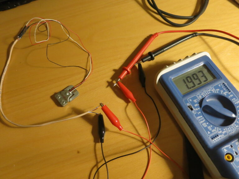
In my previous post I covered how to choose matching resistors for the Load Sensor to convert the Load Sensor into a Load Cell that can be wired into Sparkfun’s Load Cell Amplifier. In this post, I nearly finish building the breadboarded circuit and start transferring it to a soldered protoboard.
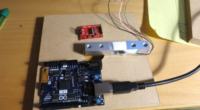
In my previous post, I worked through the calculations of weight and center of gravity when using four Load Cell Amplifiers instead of one. In this post, I build the circuit for the first of the four Load Sensor / Load Cell Amplifier combinations I’ll be using.