
Earlier, I described how to build a frame for the glockenspiel. In this post, I cover the circuit that will strike each chime.
I’ve successfully tested the glockenspiel control circuit. It’s an Arduino Mega 2560, a Sparkfun Wifi Shield, and 19 repetitions of a simple solenoid control circuit.
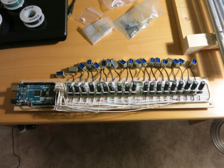
(by the way, the solenoids in the photo are there only for testing. In the finished Glockenspiel, there will be long wires connecting the circuit to the glockenspiel-mounted solenoids.)
I started from this drum control circuit described in Make Magazine (image is from Make Magazine).
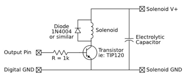
Then I chose a few specifics: at TIP120 transistor, a 1000uF capacitor, a 1N4004 diode, and a 5V solenoid from Sparkfun. …and did 19 copies of the circuit; one per chime in the glockenspiel.
My main concern was whether the solenoids could be powered only by the VIn pin on the Arduino when powered via a 9V 650mA wall power supply. Turns out the answer seems to be “Yes”: the 1000uF capacitor prevents the solenoid from drawing down the main power enough to reset the Arduino, and the power consumption of the solenoids (see below) is easily supported by the power supply. (Update: I’m a little skeptical about the adequacy of the power, because the finished glockenspiel seems to erase the SD card occasionally, likely because of noise caused by the solenoids.)
To avoid burning out the solenoids each one is powered only a few milliseconds at a time. This causes the solenoid to hit the chime with just enough power to ring nicely, but not too loudly. The math’s pretty straightforward: the data sheet provides the maximum average wattage that the solenoid can dissipate and the minimum resistance of the solenoid. The power supply puts out about 9V. Working out the numbers, it looks like for quickly-paced music, a 6ms-per-strike is about the maximum the solenoid should support (conservatively). Playing most music, this shouldn’t be anywhere near the maximum power the solenoid can support.
You can see a video of the test of this circuit, showing that it can powerup, power down, and run through each of the solenoids.
Next, I write the code to read the music.