
NOTE: Go to the updated post Making a 3D Printed Name Badge, Version 2. The tools have improved and changed in the years since I’ve written this original post.
Last month at the Portland OR 3D printing Meetup, someone suggested we should all make our own name badges so Shashi wouldn’t need to bring as many “Hello, My Name Is” paper tags to the Meetups. Game On!
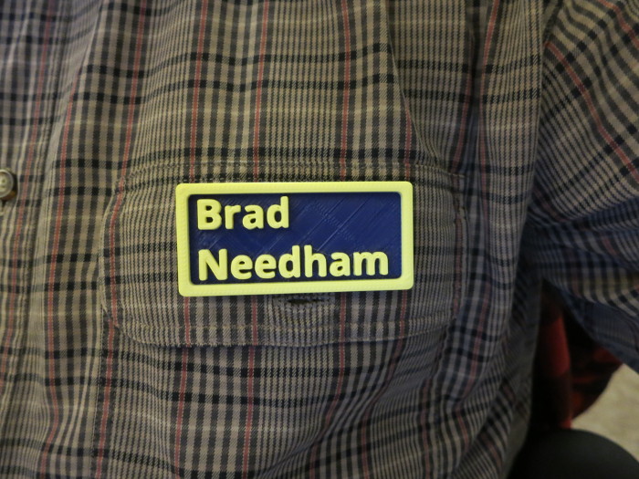
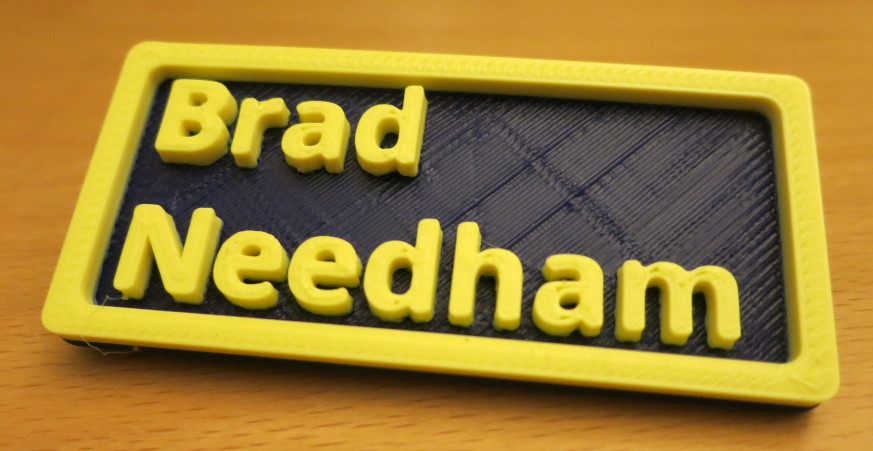
In this post I explain how to make your own, two-color 3D Printed name badge just like mine.
Tools and parts I Used:
- Inkscape 0.91, a free and open source vector graphics editor similar to Adobe Illustrator.
- FreeCAD 0.16, a free and open source 3D CAD editor similar to Fusion 360, Sketchup, and Tinkercad.
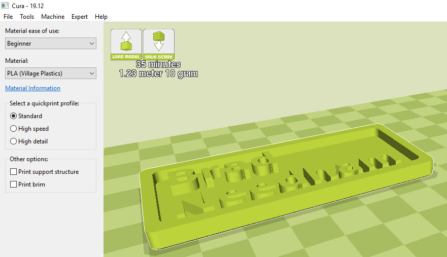
- Cura 19.12, a free and open source Slicer, that converts the output of FreeCAD (and many other programs) to codes a 3D printer can understand. I use the Lulzbot Edition of Cura.
- Lulzbot Mini, an open source 3D Printer.
- Two contrasting colors of PLA filament for your printer. I used a blue background and yellow lettering. I used PLA just because I like PLA. You don’t need a dual-extrusion printer.
- Blank tie tacks and pin backs, such as these pins available on Amazon. I used some pins I bought at Joann.
In brief, the process is to 1) Create your name in Inkscape 2) Convert the text of your name into 3D text in FreeCAD 3) Add the base and rim of the badge to your name 4) print the badge, swapping filament in the middle of the print to make your two-tone badge 5) Glue a couple of pins on the back, and you’re ready for Meetups!
Create your name in Inkscape
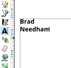
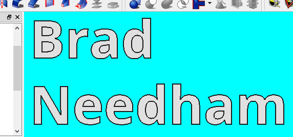
Open Inkscape. Use the Text tool to type in your name, in two lines, starting in the upper-left of the page.
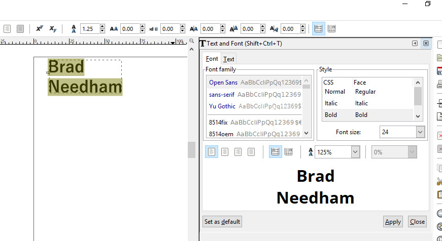
Using the Text tool, select your name (click and drag across it), then set its font and size using the Text / Text and Font… menu item. Then click Apply, and close the text dialog. A tip: Sans Serif fonts will print better than Serif fonts, because those tiny Serifs are hard for most printers to print accurately.
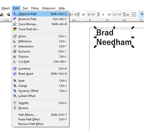
Select your name object using the Selection Tool (the Arrow), then choose the Path / Object to Path menu item. That converts the characters of your name into lines that FreeCAD will understand.
Save the file as an .SVG (Scalable Vector Graphics) file. For example, save it as myname.svg. Close Inkscape.
Convert the text into 3D text in FreeCAD
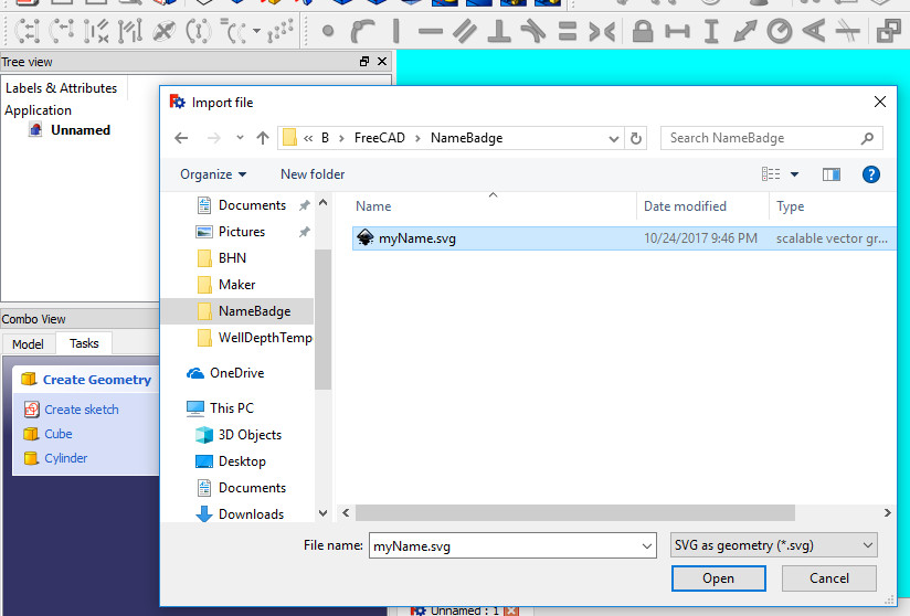
Open FreeCAD. Create a new File, then File / Import your SVG file (e.g., myname.svg), making sure that the File dialog’s SVG as Geometry (*.svg) item is selected.
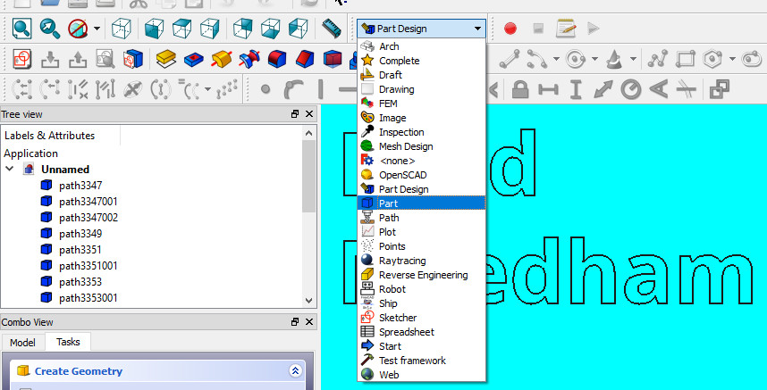
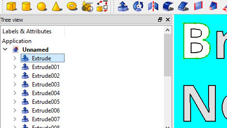
Your FreeCAD file now consists of a bunch of Paths, with names such as path3347, path3347001, etc. Next we will extrude these Paths into 3D text.
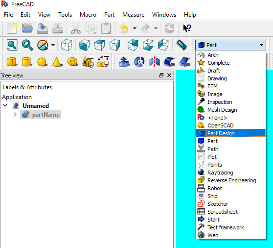
Select the Part workbench.
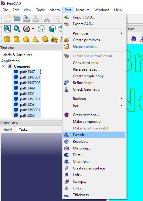
Select all the Paths that make up your name, then select the Part / Extrude… menu item.
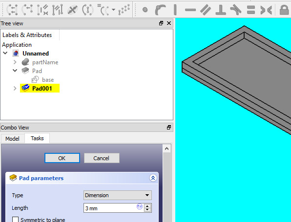
In the Extrude dialog, make sure the X, Y, and Z are set to 0.0, 0.0, and 1.0 respectively – that tells FreeCAD to extrude in the Z direction – then set the Length to the height you want your letters to be. I used 3 mm because that’s thick enough for me to swap filament easily, and thin enough to look nice.
In that dialog, also check the Create Solid box.
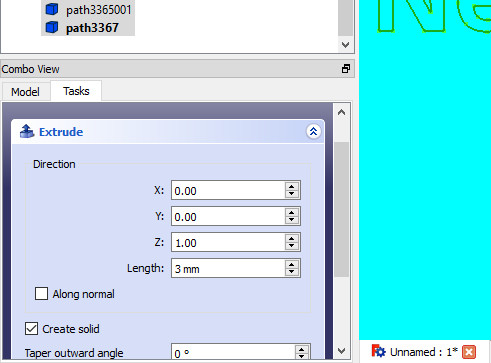
Click the Ok button of that dialog (at the top of the dialog).
Now you have extruded text, but it looks odd: there are no holes in the letters. The reason is that each hole is now a separate, extruded object that needs to be removed from its letter.
Let’s create the holes in the letter “B” first. This operation is a little tricky because the letters have names like Extrude001 instead of “B” or “upper hole in B”.
Select each ExtrudeNNN item until the letter “B” becomes highlighted. Note which Item that is. In our example, it’s named “Extrude”. Do the same to find the names of the upper and lower holes in the “B”. In our example, those holes are named “Extrude001” and “Extrude002”.
Select the Extrude item corresponding to the letter “B”, then Ctrl-click the Extrude item corresponding to one of the holes in the B (for example, “Extrude001”. Then select the Part / Boolean / Cut menu item. Now the “B” has a hole in it.
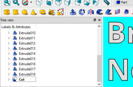
Notice that the result of the cut (the “B” with one hole in it) is now named “Cut”. As you make each subsequent hole, the result will be named Cut001 or such.
Because the “B” has two holes, now select the Cut item corresponding to the “B” with one hole, then Ctrl-Click the Extrude item corresponding to the second hole in the “B” (Extrude002 in our example) and select the Part / Boolean / Cut menu item. Now the “B” has two holes in it, like it should.
Repeat the process for all of the other letters in your text that should have holes.
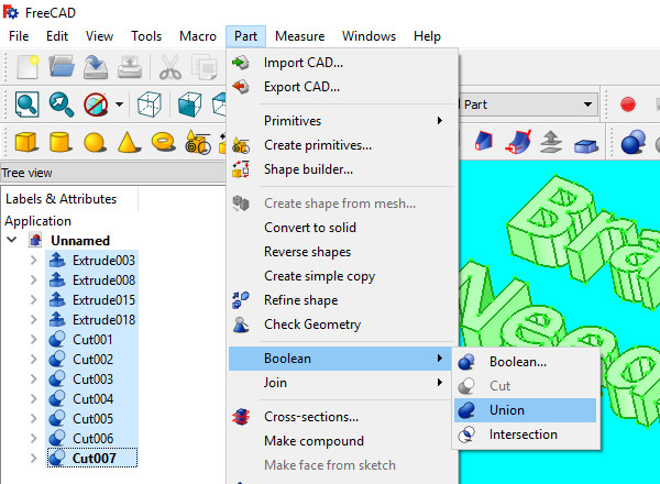
Finally, select all the finished parts of letters (items named “Extrude001” and “Cut001”, etc.) and select the Part / Boolean / Union menu item.
Now your name is a single Part in FreeCAD. You might want to rename it to something like “partName”.
Add the base and rim of the badge
Ignore your name text for a bit. In FreeCAD you can select it, then press the Space key and it will disappear from view.
Select the Part Design Workbench.
For brevity, I’ll gloss over some of the details of creating the base, because it involves FreeCAD operations you can easily learn from various online tutorials.
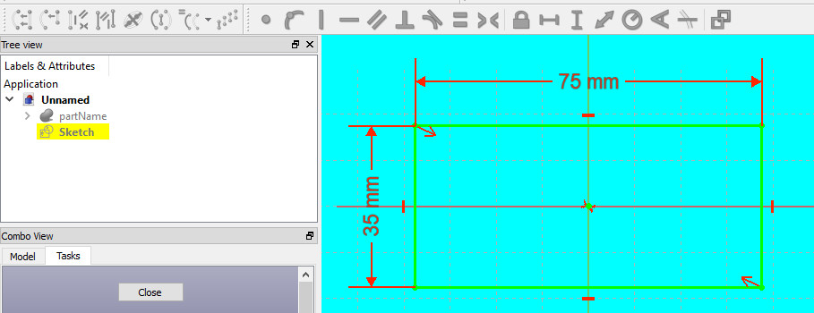
Create a FreeCAD XY-plane Sketch of a rectangle. This will become the base of the badge. I chose a rectangle 75 mm x 35 mm.
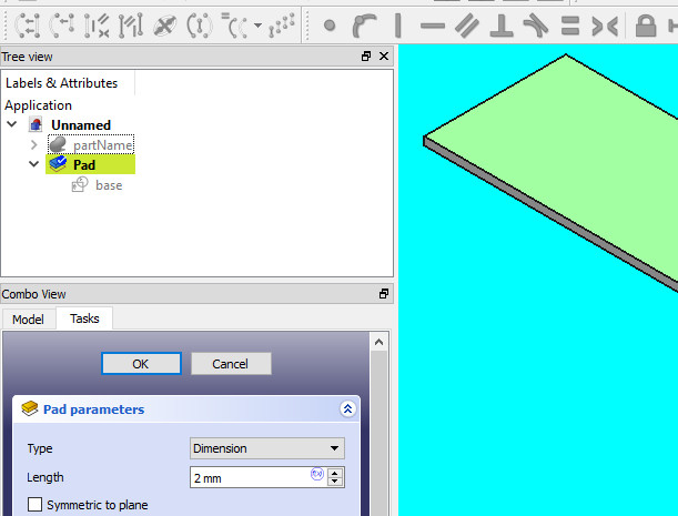
Extrude that base to the thickness you like for your badge. I chose 2 mm because that’s thick enough to be strong and thin enough to look nice. Then click Ok.
Next we’ll make the badge rim. I like a rim on the badge because it highlights your name and encloses the text of your name.
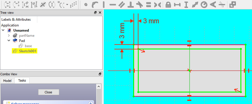
Select the top of the base and create a Sketch based on that surface, consisting of an outer rectangle and inner rectangle. I chose to make the rim 3 mm wide because that’s about the thickness of the strokes in the text of my name.
Extrude that rim to the same thickness as your extruded name text. For example, I extruded my name text 3 mm, so I’ll extrude the rim 3 mm.
Next we’ll position and scale your name so it fits into the badge base and rim. We’ll Clone the text so that we can adjust its size.
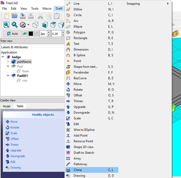
Switch to the Draft Workbench, and make your name visible again (select it and press Space).

Select the name text, then select the Draft / Clone menu item.
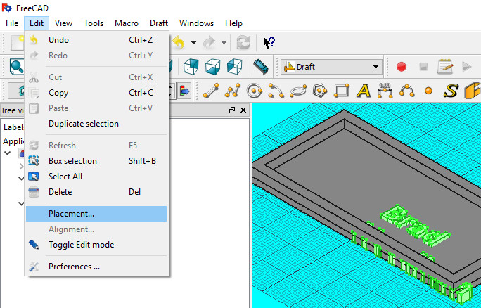
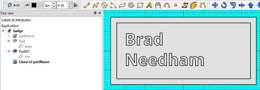
Switch back to the Part Workbench, hide the original name text (the Part you Cloned), and select the Cloned text (named something like “Clone of partName”).
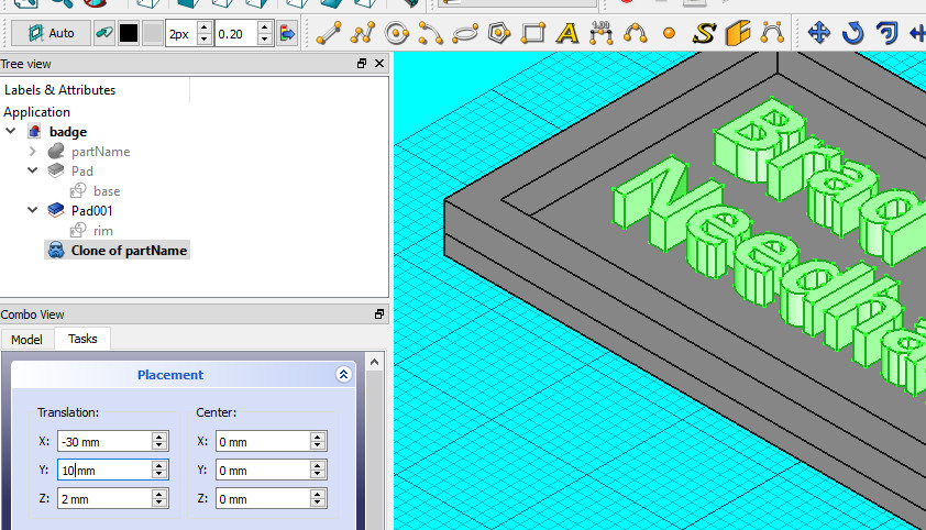
Select the Edit / Placement… menu item.
Set the Z Placement to match the thickness of your base. In this example, the base is 2 mm thick, so we set the Z Placement to 2 mm.
Then pick X and Y Placement values that put your name text roughly where you want it on the badge, and click Ok. Don’t worry about the text size or exact placement just yet.
In the Top view of your badge, you may find your name isn’t the size you’d like. In this example, the name is a bit small.
To resize the text: Select the Cloned text, select the View / Panels / Property View menu item, then adjust the Scale X and Y values until the text is the size you want. In this example, I chose an X and Y scale of 1.5. Use the same value for X as you used for Y so the text is undistorted.
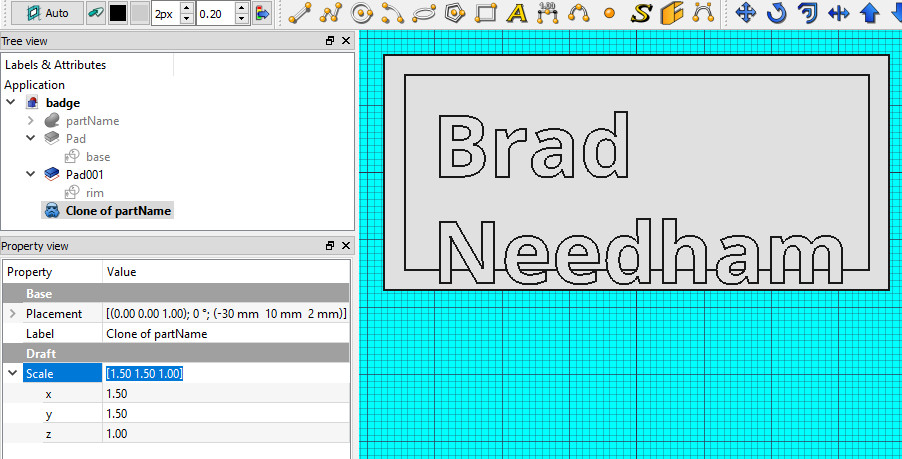
Of course, the text is now off-center. Use the Edit / Placement dialog like you did above to place the text exactly where you want.
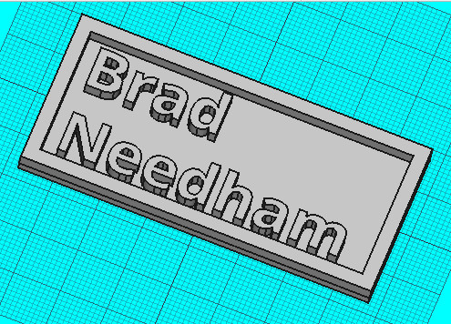
Briefly, now you can make a Part from the base and rim (“Create Simple Copy“), and Fuse the text, base, and rim (Part / Boolean / Union).
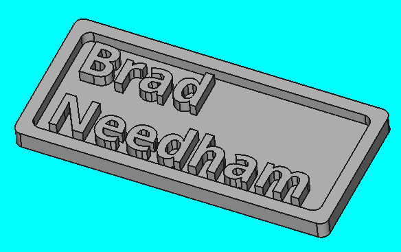
Now you can do some simple FreeCAD ornamentation, such as Filleting (rounding) the corners. Finally, File / Export… the badge from FreeCAD as a .STL file named, for example, badge.stl.
Print the Badge
Choose two colors of filament, that contrast well, for your badge: one color will be the base (the background) of the badge, the other will be the name and rim color.
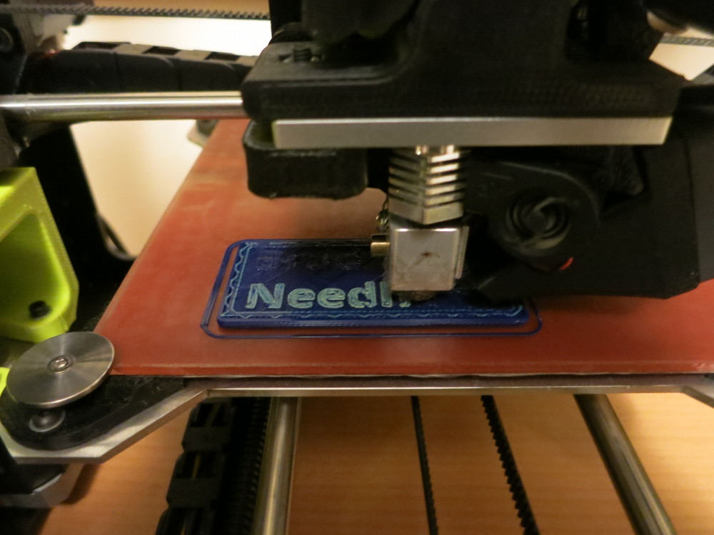
Load your printer with the base color filament you’ve chosen, and start the print.
Once the printer has finished printing the base and has started to print the letters of your name, pause the print, switch to the second color of filament, and resume the print.
Be sure to avoid moving the print head as you switch the filament. If you accidentally move the head, the rest of the print will be unpleasantly offset from the first part.
If you have to choose between swapping the filament too early and too late, choose to swap the filament a bit late. It’s ok for your letters to have a couple layers printed in the base color.
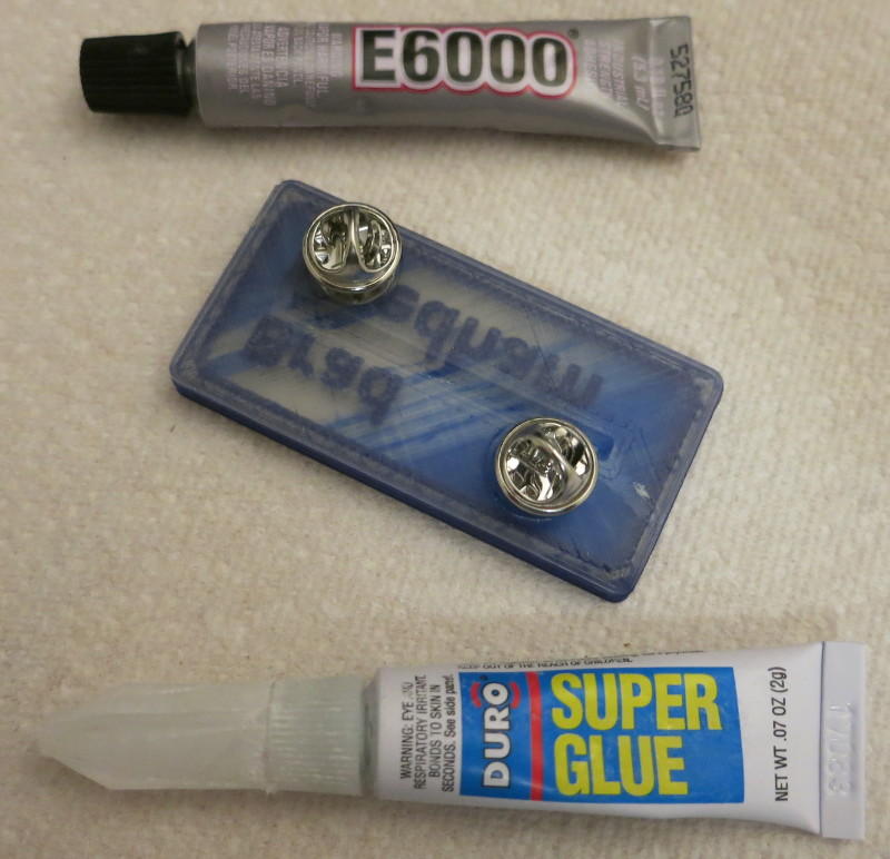
Once the badge has finished printing, glue two tie-tack pins to the back of the badge. I used E6000 to glue the parts; I’ve had mixed success with Super Glue.
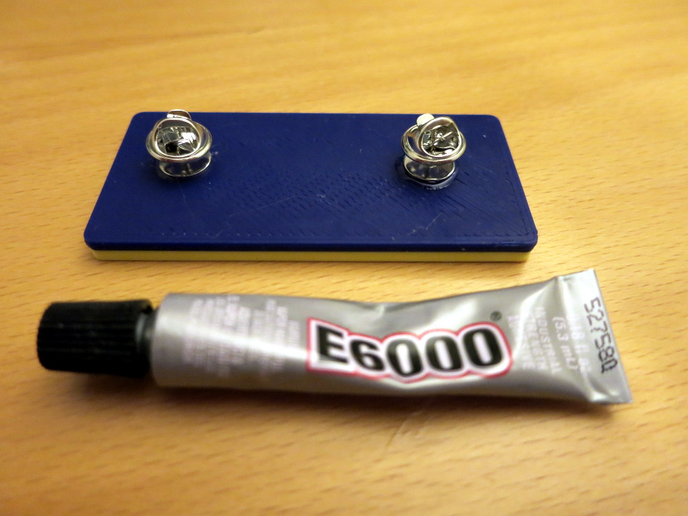
Once the glue has cured (E6000 takes a day to cure), your badge is ready to wear!
Now that you know how to make a basic 3D printed badge, you can make more interesting badges. For example, I want to make my next badge with a non-rectangular outline, such as a splat of ink.
Outtakes and links
(Was it Maz who said this?) Badge Magnets are great alternatives to pins, because they don’t punch holes in your clothes.
The first time I tried this two-color printing method, I switched the filament too soon. I was fooled because the printer started to print some of the letters, but it was (clearly) still printing the long, angled lines of the base.
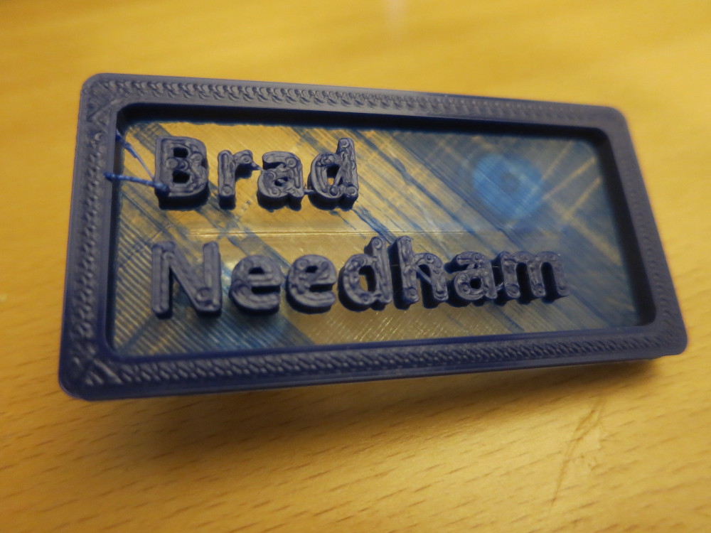
You’ll also notice that I was using clear filament as a background. That works fine if your clothes happen to contrast with the text color, but otherwise makes your name hard to read.
I tested Super Glue and E6000 on that bad first badge. Surprisingly, they both seem to work equally well in this situation.
If you prefer Tinkercad over FreeCAD, see Matthew Ebisu’s Instructable. Matthew also suggests having fun and printing your name in glow-in-the-dark letters!