
As I said in the previous post, I’m using 4 Sparkfun load sensors, a Load Sensor Combinator board, a Load Cell Amplifier board, and an Arduino 101 (since obsoleted) to build a scale I can put under our dog’s bed, to passively weigh her whenever she’s in bed.
In the previous post, I cut the base for the scale from a sheet of plywood. In this post, I’m assembling the circuit.
To begin with, the load sensors come with about 14″ of wire attached. Because my scale has a 20″ radius, I need to solder more wire to each load sensor wire. For convenience I used some (very) old CAT3 cable I have lying around. CAT3 cable was made for old phone lines, and has two twisted pairs of cables inside an insulating sleeve.
First, so you don’t forget, cut a length of heat-shrink tubing for each load sensor wire, and slip it over the wire. I admit I’ve soldered wires together in the past and too late discovered I didn’t add the heat shrink tubing before I soldered. Choose a tube diameter about twice the diameter of the wire you’re using.
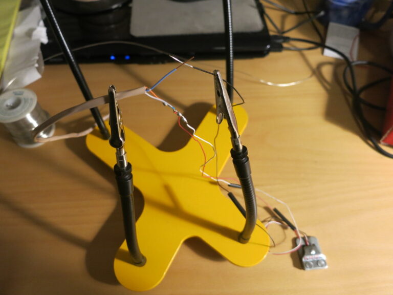
I really like the gooseneck quad soldering tool here. It’s similar to Sparkfun’s Third Hand Kit.
You can look up how to solder wires together. The method I prefer is to hold the two wires in an “X” pattern, then wind each one around the other, then solder. This gives a nice “in-line” solder.
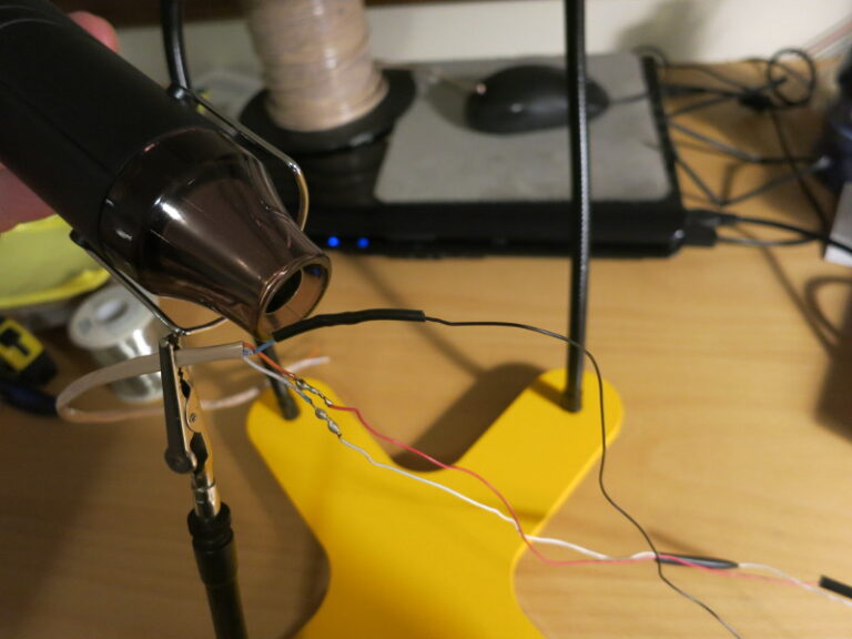
Once the soldering is done, slide the piece of heat shrink tubing into place and heat it to form a nicely insulated connection. I like using a heat gun rather than messier things like a hair drier or matches.
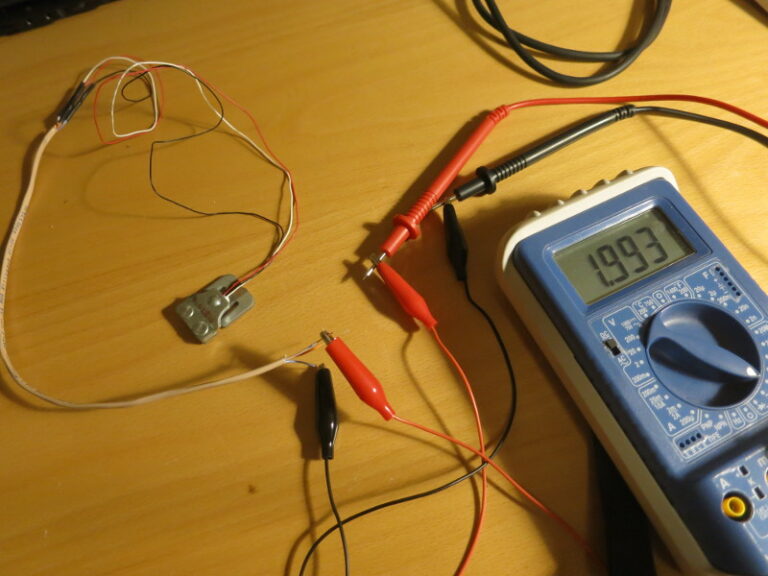
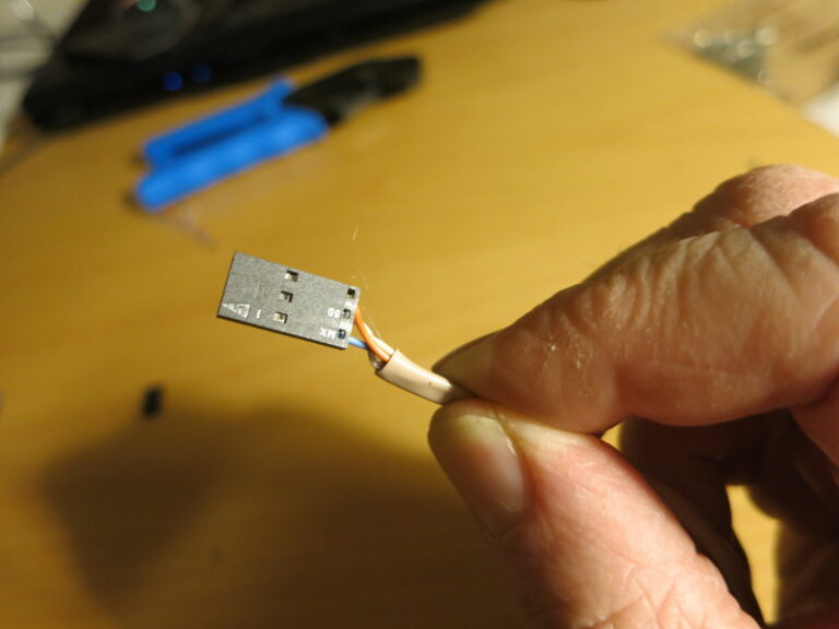
Once the connections are done, it’s good to double-check the connections with a multimeter. In this case, the Load Sensor’s White-to-Blue/Black resistance should be about twice the resistance between White and Red or Red and Blue/Black.
The Load Sensor board and Load Cell Amplifier board come without headers. I like to connect everything with removable connections (like a header and plug) in case I need to replace or fix a part later. So the next step is to solder headers on all the connections of these two boards.
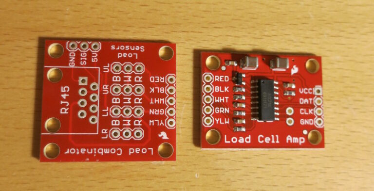
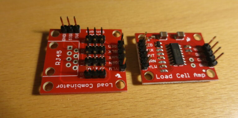
It turns out I didn’t need to put headers in for the side pins labeled GND, SIG, and 5V; those are for an optional temperature sensor.
The next step is to crimp Molex connectors onto the wires. I’m sure I’m not doing this like a pro, but it works well enough.
To start strip a small amount of insulation from the wire.
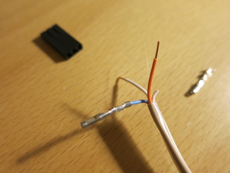
Then use crimping pliers to crush the crimp connector around the wire. The outside crimp should grip the insulation of the wire; the inside crimp should grip the uninsulated wire. I’ve recently switched from non-ergonomic pliers to crimping pliers that automatically release when you’ve pressed hard enough – old-style pliers can contribute to repetitive stress injuries, which you want to avoid.
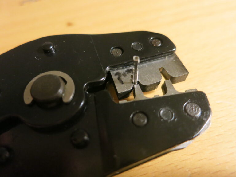
With these pliers there are 3 wrong ways to crimp the connector, and one right way. You may need to experiment to find which jaw to use (front or, as pictured, back) and which way the connector has to face (the left or, as pictured, right side of the pliers).
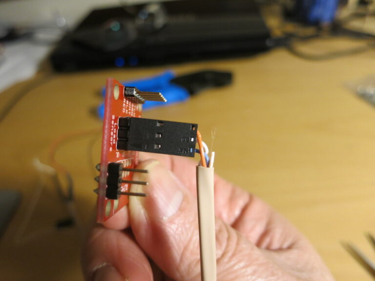
Once you have all the pins for a connector crimped onto their wires, it’s time to press the connectors into the shroud (the black plastic cover). Line up each pin’s “barb” with the hole in the shroud so that once you slide the pin in a bit, it latches.
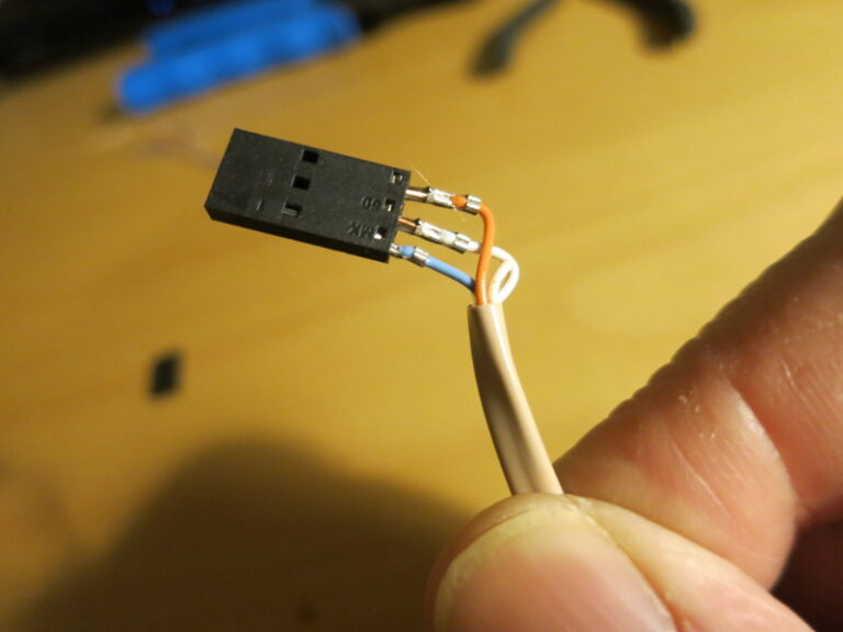
Once you have pushed all the pins to the first stop, you then can push them further to the second, final stop. You may need to use needle nose pliers to push the end of the wire until each “barb” clicks into place. Having all the pins click into place means that they won’t pull out accidentally, and you have a nice, solid connector.
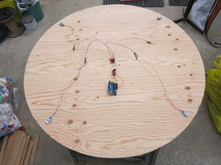
You need to connect each load sensor to the Load Sensor Combinator board, the Combinator board to the Load Cell Amplifier board, and the Amplifier board to an Arduino. I’m first using an Arduino Uno to get the weight measurement working before I switch to an Arduino 101.
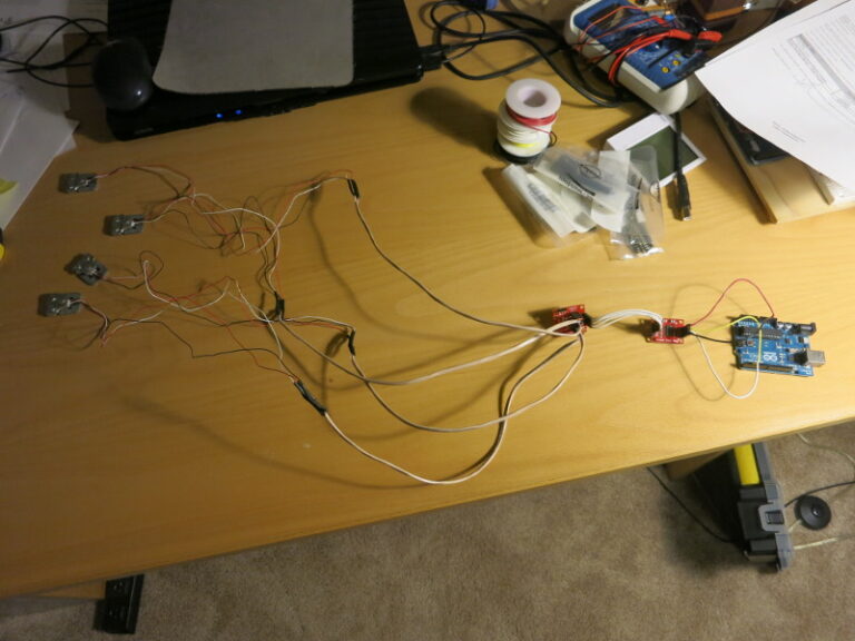
At this point, I did a test layout of the circuit on the plywood base. I wanted to double-check that the Load Sensor wires were long enough before I started the mechanical work.
In my next post, I complete the assembly of the scale.