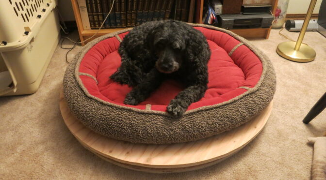
In my previous post I changed the uploader app to run when the Raspberry Pi turns on, and installed the scale under Pippa’s dog bed. In this post, I get interesting data from the scale.
The scale has been running for a little over a week now, and has been surprisingly reliable for a first version. There is some sort of bug in which, every few days, the scale stops supplying new data BLE notifications to the gateway. I plan to refactor the scale and gateway to avoid that, but that’s another post.
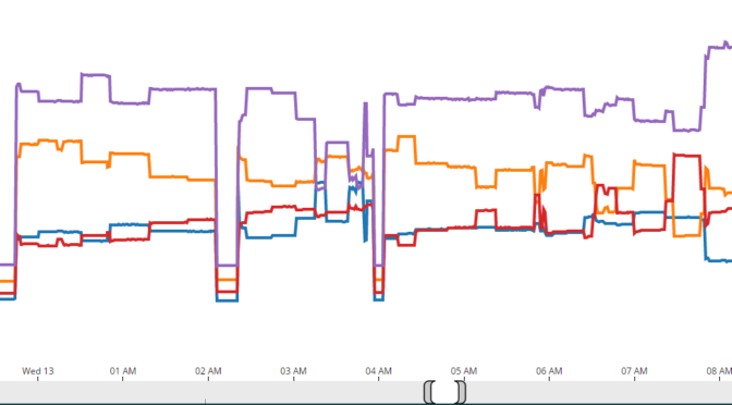
Today I looked at the data and saw some very interesting things.
In my previous post, I wrote the Raspberry Pi Node.js code to upload data from Pippa’s dog bed scale to data.sparkfun.com (update: site is down in 2021). This post covers how to make a Node.js program run automatically when the Pi is turned on. Oh, and at the end I installed the finished scale under Pippa’s bed.
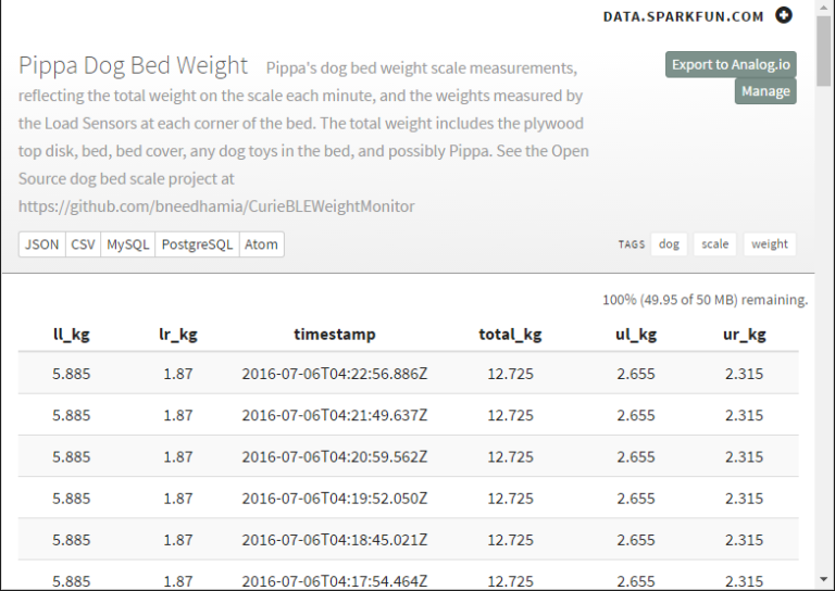
In my previous post I finished the hardware for the scale and calibrated it. This post covers getting data from the scale to Sparkfun’s Data Warehouse (Update: by 2021 the site has been taken down).
By the way, the nRF Master Control Panel (BLE) from Nordic is the perfect tool for debugging Bluetooth Low Energy devices and messages. It understands a pile of standard Bluetooth data types as well as the Physical Web, so it’s a quick way to find out whether your Arduino project is sending the right data.
In my previous post, I designed and printed a Centering Guide to line up the top and bottom pieces of the scale. In this post, I finish assembling the scale.
Now that I have the Load Sensor Holders that I designed and printed, I drilled mounting holes in the blocks that will hold the Load Sensors.
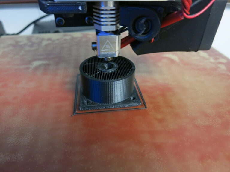
In my previous post, I did a little woodworking on the scale. In this post, I start designing a 3D printed part that will keep the top of the scale centered on the bottom.
Ever since I measured the center of gravity of the top plywood circle, I’ve been puzzling through how to make sure that center of gravity stays centered on the bottom part of the scale. Without some sort of connection between the top and bottom plywood circles, the top will inevitably slide over time, messing up all the center of gravity calculations. On the other hand, if this connection between the top and bottom has much vertical friction, it will take some of the load of the scale, throwing off the weight calculation.
In my previous post, I 3D printed parts to hold down the Load Sensors. In this post, I correct the counterbored holes that keep the nuts from protruding below the bottom of the bottom piece of plywood.
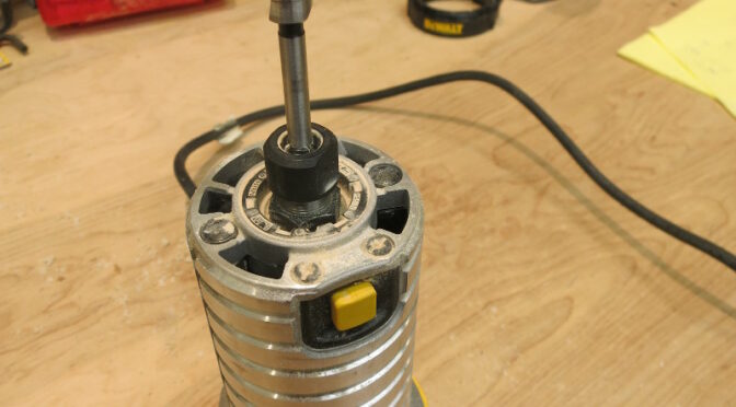
In the woodworking post, I used a router to cut counterbore holes on the bottom side of the bottom piece of plywood. These holes hold the nuts that hold the circuit boards.
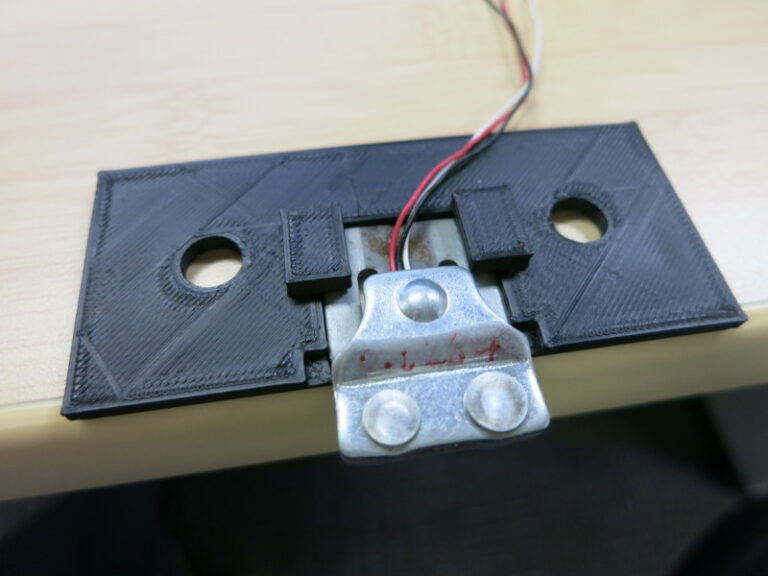
In my previous post I soldered the weight scale parts to a proto-board. In this post, I design and 3D-print the part that keeps the Load Sensors from slipping.
The Load Sensor is an oddly-shaped thing that has a few tricky constraints: the T-shaped part in the middle must be free to bend downward (my wooden mounts take care of that), and I don’t want it to slide out of place horizontally or tilt off of its position when I’m putting the top plywood piece on the scale.
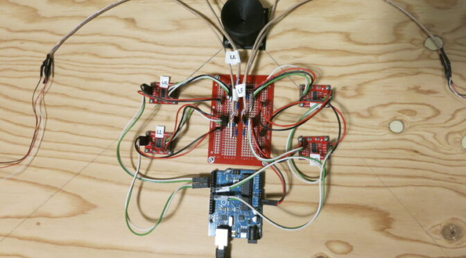
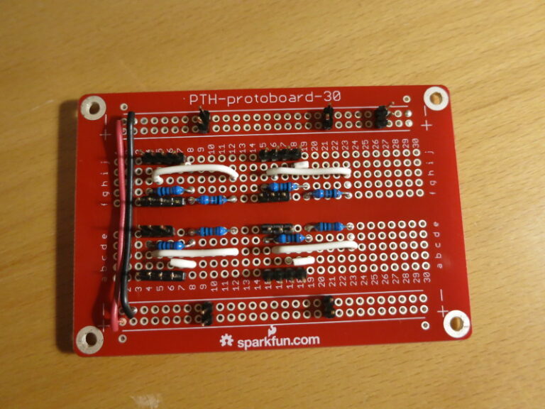
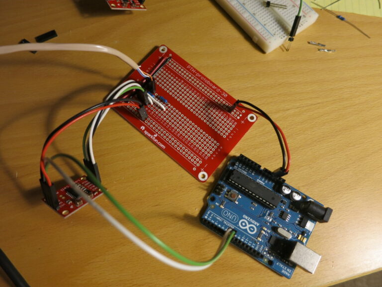
In my previous post I described how to use long break-away headers, and started soldering the circuit together. In this post I finish transferring the scale circuit from the breadboard to a protoboard, and do a quick test mount of the circuit on the plywood scale base.
A reminder: I found that the Load Cell Amplifier was (by design) so sensitive to changes in resistance that just touching the resistors on my solderless breadboard caused large changes in the Amplifier output. So I wanted to solder all the parts down.
It’s a good time to recap: This project is a scale that will sit underneath my dog Pippa’s bed, so that I can measure her weight automatically, at night while she sleeps. The project-in-progress is Open Source, at my CurieBLEWeightMonitor Github repository.
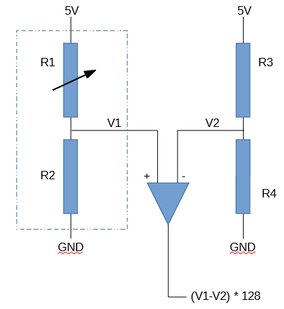
In my previous post I covered how to choose matching resistors for the Load Sensor to convert the Load Sensor into a Load Cell that can be wired into Sparkfun’s Load Cell Amplifier. In this post, I nearly finish building the breadboarded circuit and start transferring it to a soldered protoboard.
In my previous post, I worked through the calculations of weight and center of gravity when using four Load Cell Amplifiers instead of one. In this post, I build the circuit for the first of the four Load Sensor / Load Cell Amplifier combinations I’ll be using.