
In my previous post I described the electronics of the Dog Bed Weight Scale. In this post, I’m doing the final woodworking and assembly – at least enough assembly to test the thing.
First I needed to design some sort of support for the load sensors. Because of the design of the sensor – a “T” bar surrounded by a “C” shaped bar – I needed to make blocks that were 1) tall enough to keep the top piece of plywood from resting on or crushing the electronics and 2) cut out to allow the “T bar to bend below the “C” shaped part as weight was added. You can find plenty of videos of people trying to use load sensors by mounting them on a flat surface; that won’t work.
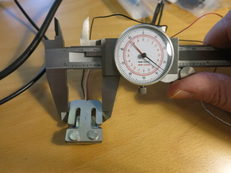
So, to design the blocks, I first measured the dimensions of the load sensor, using a Caliper, then drew up a simple design from that.
Meanwhile, I drilled the mounting holes for the boards. Because the plywood base is so large (~41″ in diameter), I couldn’t use the drill press. So to make nicely perpendicular holes, I used a Drill Guide. I really like the one I use because it’s metal and it has a guide for each drill bit I use, creating nicely straight holes.
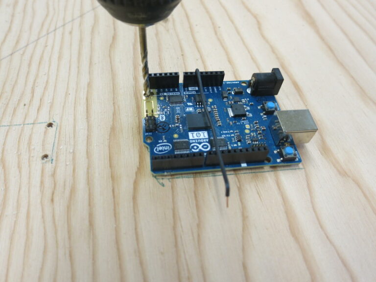
Because I was feeling a bit lazy, I didn’t measure and mark the holes for the electronics boards. Instead I used the old “mark and drill” method.
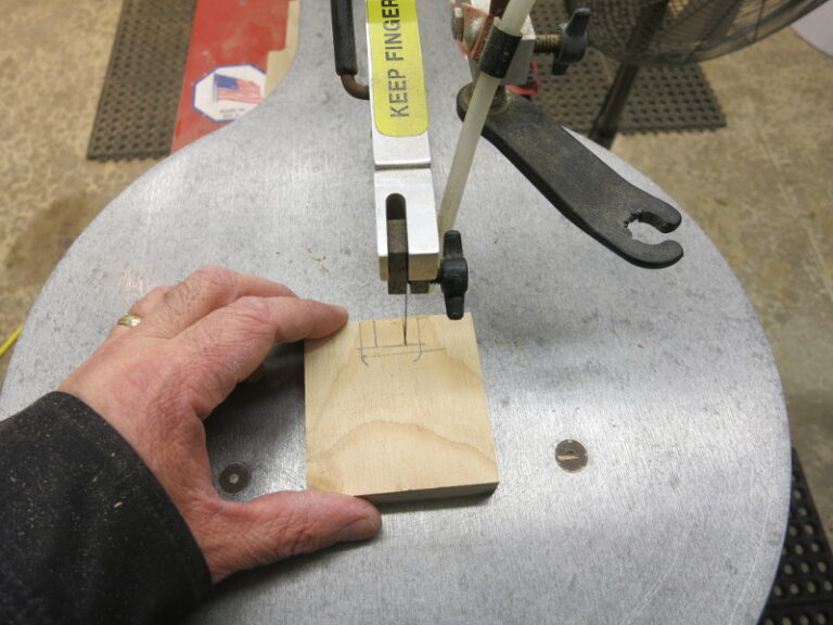
Step 1: holding the board in place, drill just enough to mark the first hole – don’t drill deep.
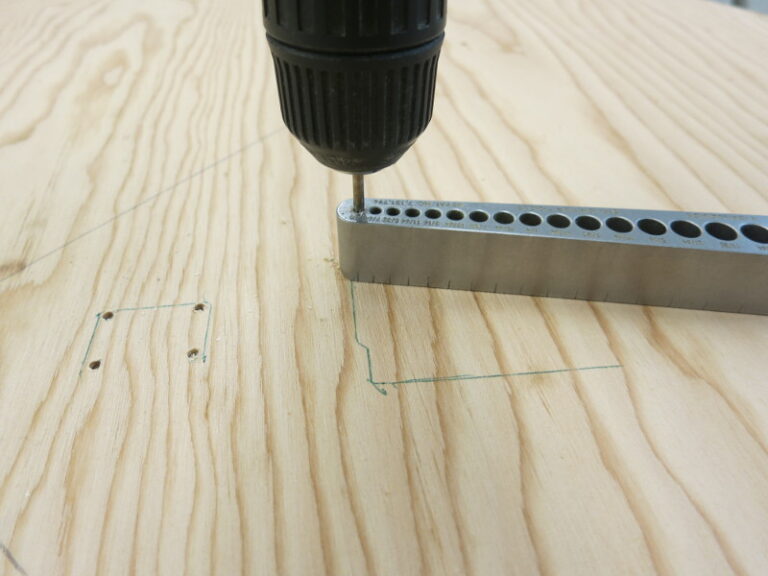
Step 2: remove the board (so the drilling doesn’t damage it) and use a Drill Guide to complete the marked hole.
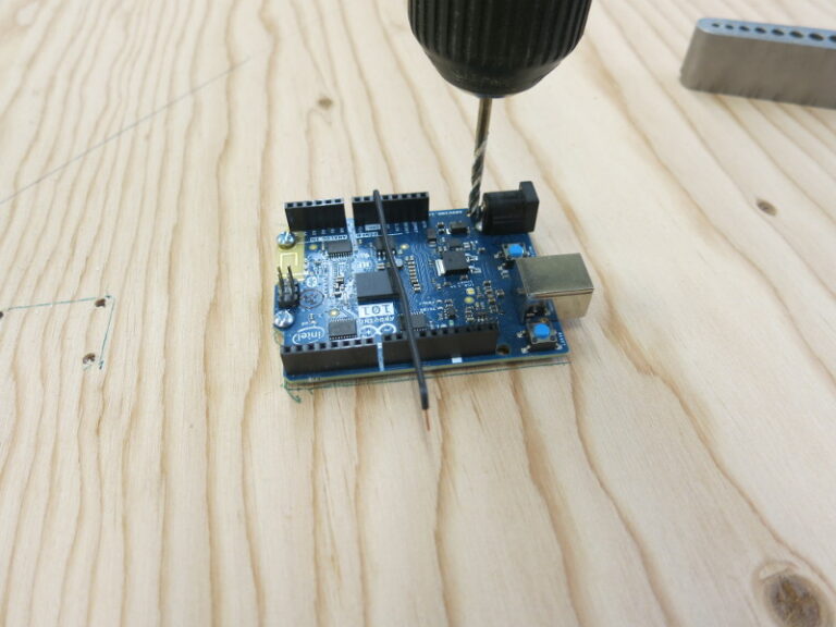
Step 3: Place the board back, drop the first bolt into the new hole, then mark the second hole as in step 1. Repeat for all the board’s holes.
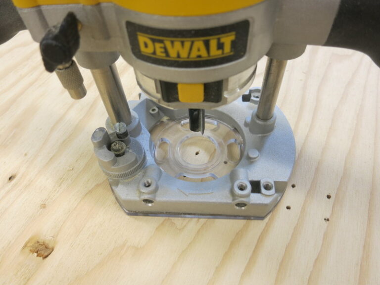
To prevent the bolts from sticking out from the bottom of the plywood, I chose 3/4″ bolts for 3/4″ plywood. Because the bolts don’t stick out, I needed to counterbore the bottom of these holes so I can attach the nuts. Again I couldn’t do this on the drill press, so I used a plunge router, set to bore just a little into the plywood.
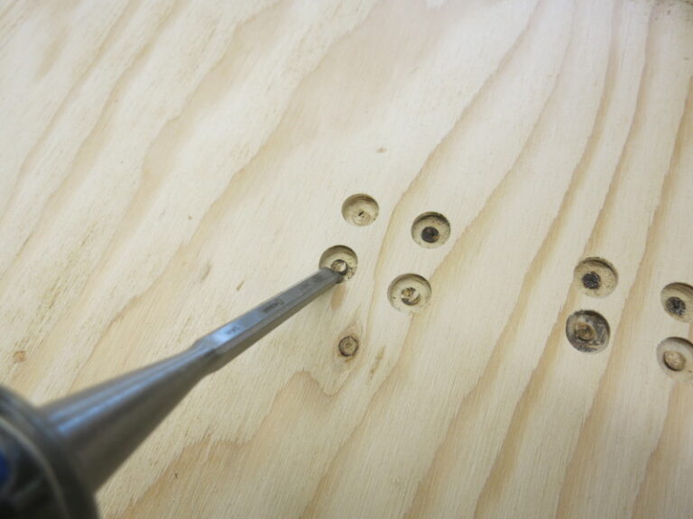
Because the router bit I used has a space in the middle, the counterbore holes leave a little disk of wood, I used a chisel to clean out the remaining little disk of wood to make the counterbore flat.
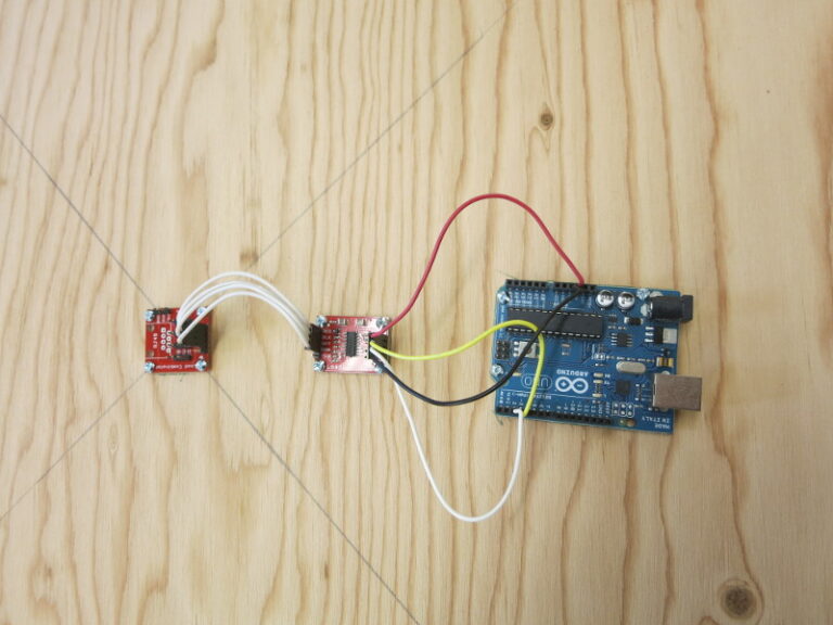
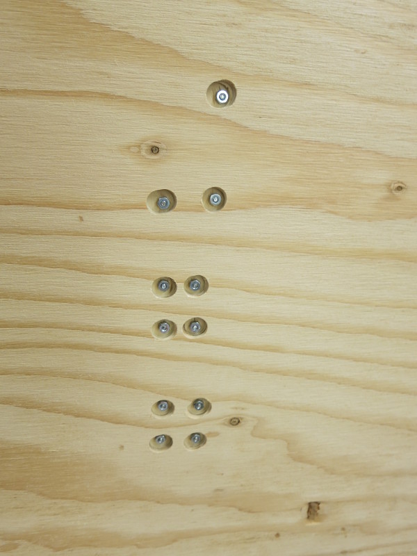
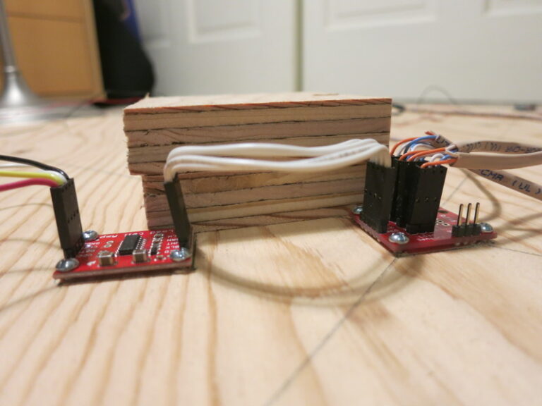
Here’s what the 3 boards look like, fastened to the plywood base.
I then cut the blocks that will support the load sensors. These are just temporary blocks, to let me test the circuit. The real blocks will (somehow) hold the load sensors in place and keep them from slipping from side to side.
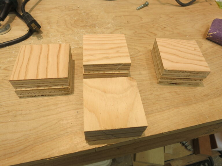
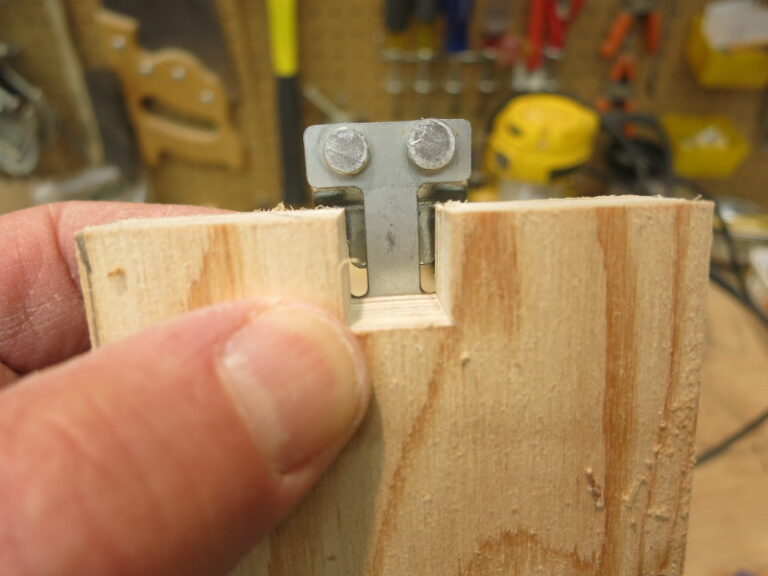
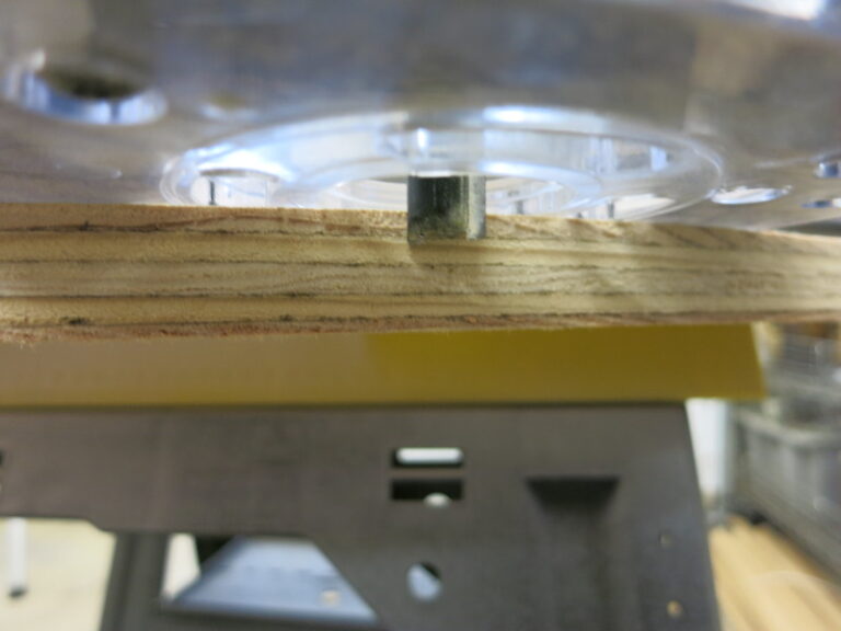
I chose the thickness of the blocks to make sure that the plywood top wouldn’t rest against or crush the electronics. See how the cross-section of the load sensor support block is taller than the circuitry.
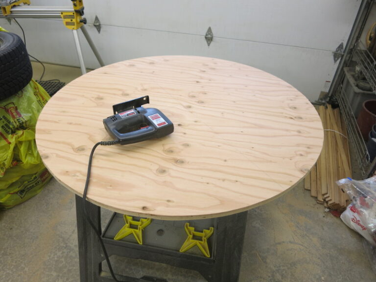
I then cut out the top plywood circle. This circle will lay on top of the four load sensors.
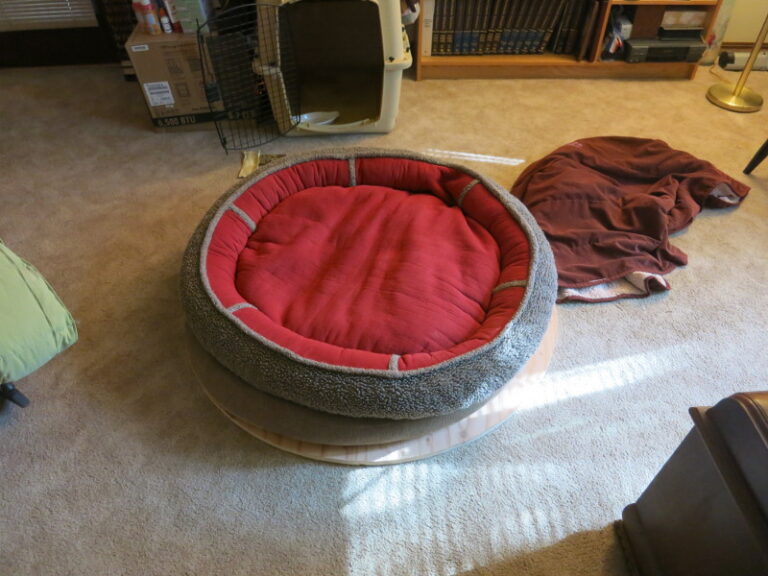
For good measure, I placed Pippa’s bed on the top piece of plywood. It’s a good fit. Yes, that’s an Encyclopedia Britannica and a VCR in the cabinet…Pippa’s a Retro Girl (seriously, what can you do with old encyclopedias? I can’t bring myself to cut them up for papier mache).
I then assembled the whole thing and started testing. Pippa helped.
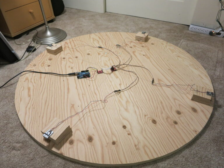
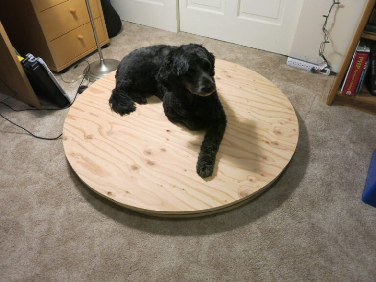
In my next post, I get to try out the circuit and try to weigh some standard weights.