
In my previous post, I designed a 3D printed sensor junction box for my well tank depth sensing project. In this post I solder… a lot.
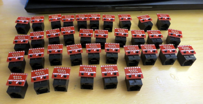
I have 36 RJ45 jacks, 36 breakout boards for those jacks, and a pile of break-off headers for those breakout boards. Each breakout board has 8 holes for the RJ45 jack pins and 8 more holes for the header pins. That’s 36 * (8+8) connections I need to make to attach the breakout boards to the jacks. That’s 576 connections to solder!
I started by snapping the 36 breakout boards onto the 36 RJ45 jacks.
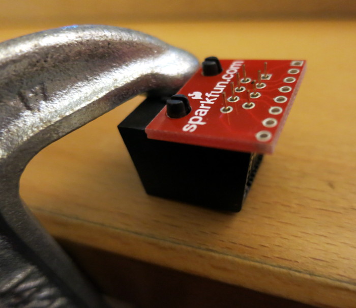
I then used my favorite technique – a lightly-tightened C clamp – to hold each jack in place so I could solder the breakout board to it. The snaps on the jack held the board in place while I soldered.
Once that soldering was done (whew!) I broke the headers I had bought into lengths of 8 pins each, then used a breadboard to hold the header pins in place while I soldered them to the breakout board.
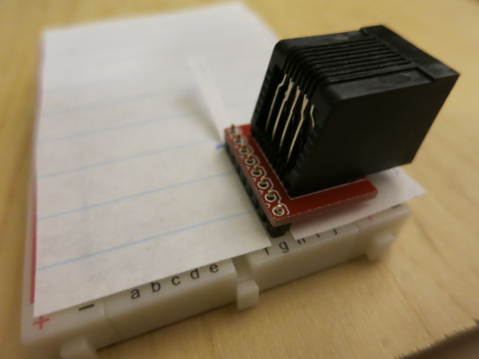
The paper sits over the breadboard to keep solder and flux from getting into the breadboard holes while I solder.
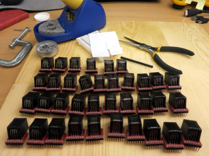
So, 576 soldered connections later the RJ45 jacks are ready to be put into the to-be-printed junction boxes. This exercise in soldering showed me that the most important thing is to keep the tip of your soldering iron clean.
As a reminder, all these jacks will be part of the sensor junction boxes that connect the MAX31820 temperature sensors to the 1-wire bus that connects to the ESP8266 Thing Dev board. The whole project code and documentation is at my WellDepthTemperature github repository.