
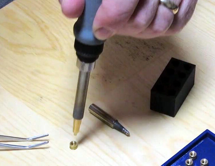
It’s time again for me to replace a couple 3D printed pieces of my Lulzbot Mini printer, so I’ve captured the details here of melting heat-set inserts into PETG 3D printed parts.
Continue reading Adding Heat-Set Inserts to your 3D Printed PartsTag Archives: soldering
Well Depth Sensing: Soldering, Soldering, Soldering!
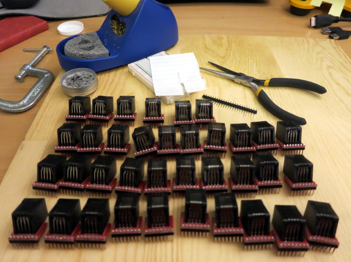
In my previous post, I designed a 3D printed sensor junction box for my well tank depth sensing project. In this post I solder… a lot.
I have 36 RJ45 jacks, 36 breakout boards for those jacks, and a pile of break-off headers for those breakout boards. Each breakout board has 8 holes for the RJ45 jack pins and 8 more holes for the header pins. That’s 36 * (8+8) connections I need to make to attach the breakout boards to the jacks. That’s 576 connections to solder!
Continue reading Well Depth Sensing: Soldering, Soldering, Soldering!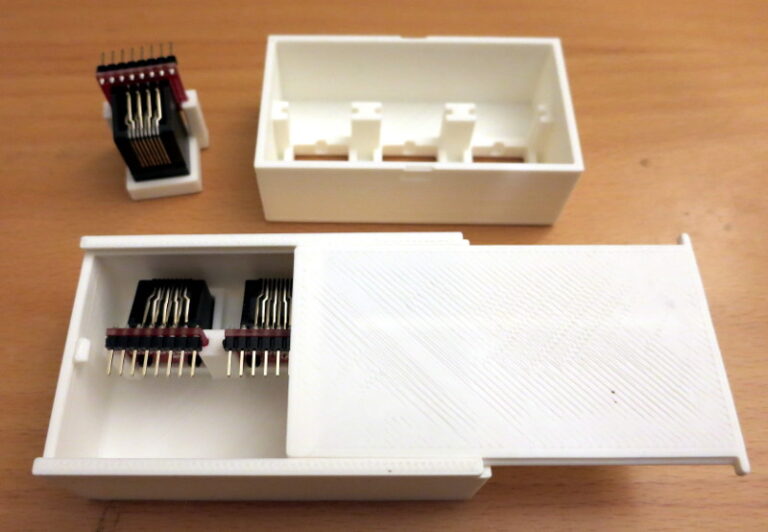
Well Depth Sensing: Mechanical Design
In my previous post, I finished the Web Service that the ESP8266 uses to upload well tank temperatures (and eventually a depth estimate) to a cloud database. In this post, I turn to the mechanical design of the case for the RJ45 jacks for the 1-wire interface.
Continue reading Well Depth Sensing: Mechanical Design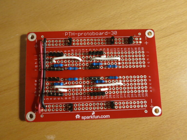
Dog Weight Scale Part 9: Soldering the V2 Circuit Together
In my previous post I described how to use long break-away headers, and started soldering the circuit together. In this post I finish transferring the scale circuit from the breadboard to a protoboard, and do a quick test mount of the circuit on the plywood scale base.
A reminder: I found that the Load Cell Amplifier was (by design) so sensitive to changes in resistance that just touching the resistors on my solderless breadboard caused large changes in the Amplifier output. So I wanted to solder all the parts down.
Continue reading Dog Weight Scale Part 9: Soldering the V2 Circuit Together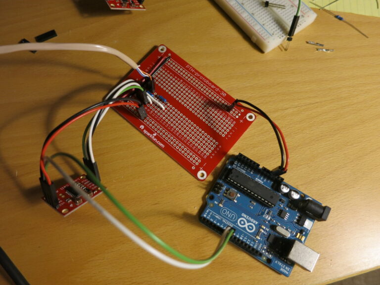
Dog Weight Scale Part 8: Electronics, Version 2
It’s a good time to recap: This project is a scale that will sit underneath my dog Pippa’s bed, so that I can measure her weight automatically, at night while she sleeps. The project-in-progress is Open Source, at my CurieBLEWeightMonitor Github repository.
In my previous post I covered how to choose matching resistors for the Load Sensor to convert the Load Sensor into a Load Cell that can be wired into Sparkfun’s Load Cell Amplifier. In this post, I nearly finish building the breadboarded circuit and start transferring it to a soldered protoboard.
Continue reading Dog Weight Scale Part 8: Electronics, Version 2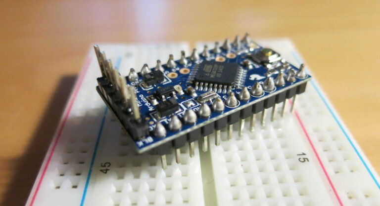
Arduino Pro Mini, and How to Solder Male Headers
I recently decided to try out the Sparkfun Arduino Pro Mini 5V board. It has almost all the I/O that an Arduino Uno has, in a much smaller board. It comes without connectors, so you can solder in whatever style connector you need. For my uses, I needed to solder on male headers that allow it to plug into a breadboard.
So I tried out a new way of soldering male header pins onto a board. First I snapped off two 12-long headers from a strip of break-away male headers. Then I plugged those headers into a breadboard and laid the Arduino Pro Mini board over them. To keep the flux and solder spatter from getting into the breadboard holes, I put a piece of paper over the unused parts of the breadboard.
Continue reading Arduino Pro Mini, and How to Solder Male Headers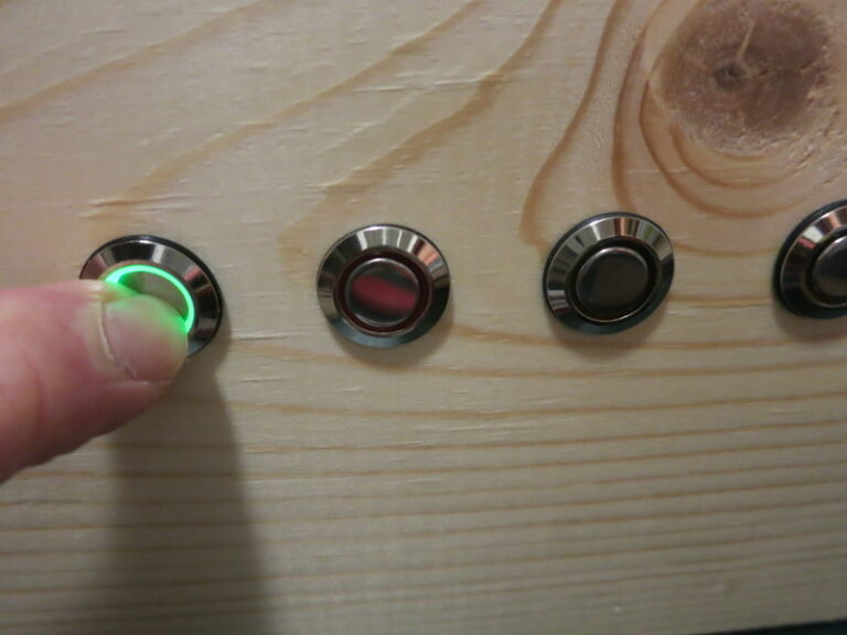
The First Switch is In
Since my last post about the glockenspiel, I’ve been taking a vacation from my vacation (aka working). Today I turned back to the glockenspiel and wired up the first of the 5 lighted switches.
Continue reading The First Switch is InNerd Christmas Tree
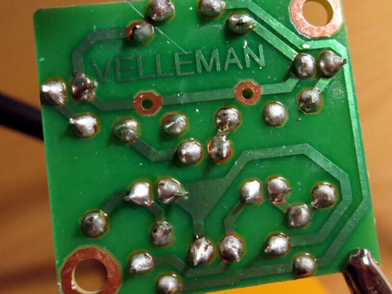
I’ve successfully assembled my second soldering kit: The Velleman MK130 ‘3D’ Christmas Tree. It’s a set of blinking LEDs that sit atop a 9V battery… or you can add some long wires and hang it as a Christmas ornament.
At any rate, it was good practice for soldering, and the result is kinda cute. See my YouTube Video of the Kit for the whole experience.
I figure I’m ready to build an Arduino proto Shield next!
Ah, the Lovely Incense of (Lead Free) Solder
Since I’ve been doing Arduino work, I’ve accumulated a few board and Shield kits that I need to put together. I haven’t soldered since college, so I decided to brush up on my rusty skills by buying one of those little electronics project kits: a Velleman MK102 Flashing LEDs kit.
Continue reading Ah, the Lovely Incense of (Lead Free) Solder