
In my previous post, I finished the Web Service that the ESP8266 uses to upload well tank temperatures (and eventually a depth estimate) to a cloud database. In this post, I turn to the mechanical design of the case for the RJ45 jacks for the 1-wire interface.
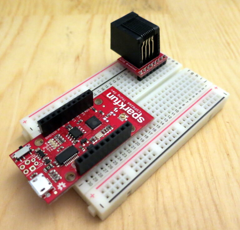
Since my last post, I’d ordered and received some RJ45 jacks and breakout boards from Sparkfun. I’m planning to use an RJ45 jack on a half-sized breadboard as the interface between the ESP8266 Thing Dev board and the 1-wire bus.
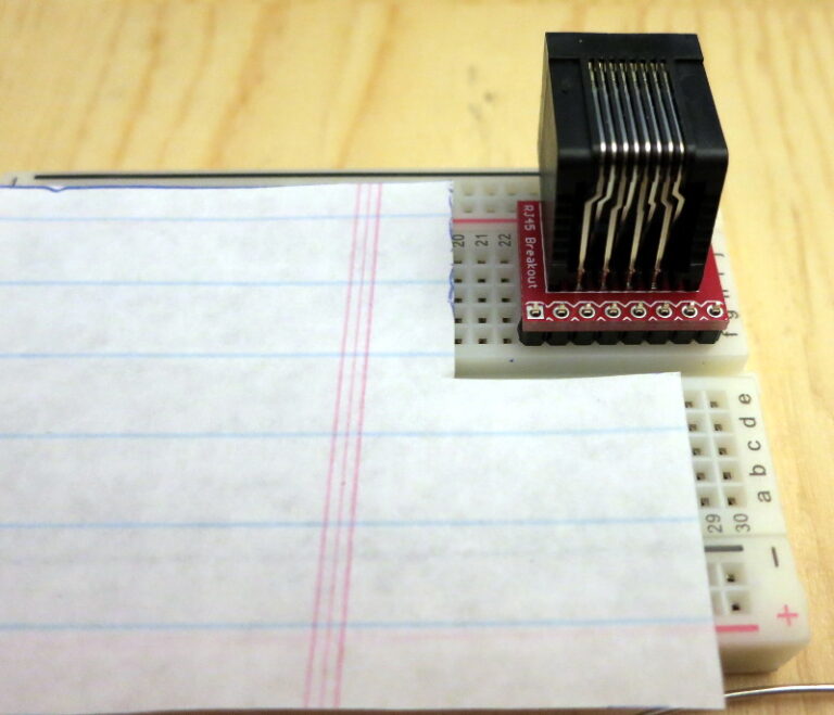
First I soldered the pins of the jack to the breakout board, then soldered the header to the breakout board, using a breadboard to keep everything stable while I soldered.
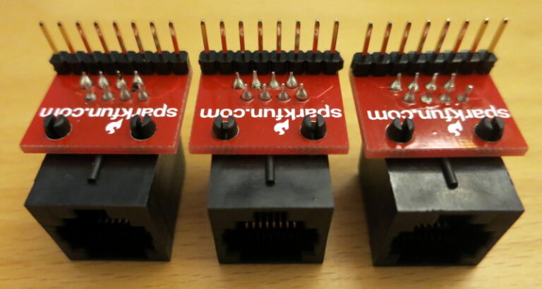
Once I finished soldering the breakout boards to the 5 RJ45 jacks I’d bought, I started to see how much easier it would be to construct each 1-wire bus sensor connection from 3 RJ45 jacks rather than doing dodgy drilling and cutting to the wall mount RJ45 boxes I’d bought earlier.
So I decided to design a 3D printed RJ45 junction box, with one box for each sensor on the 1-wire bus. Each box will accept one incoming and one outgoing Cat6 cable, and one sensor Cat6 cable.
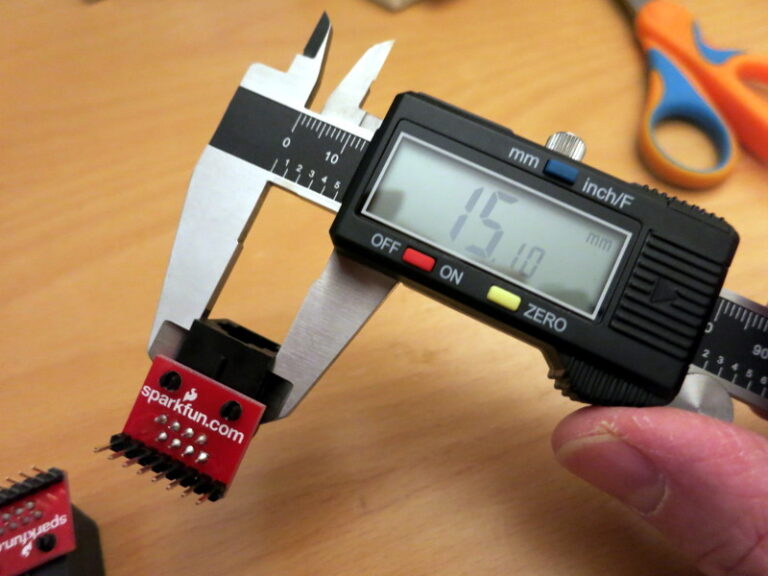
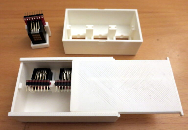
I started by measuring an RJ45 jack and breakout board, then designing a scale test print. Once that worked, I designed a simple box base to let me make the rest of the measurements. Finally, I created the sliding snap-lid junction box.
In my next post, I solder all the RJ45 jacks, breakout boards, and headers required for the 1-wire bus.