
One of the last steps of assembling a Prusa i3 MK3 3d printer is to manually adjust the Z height. As I adjusted my printer’s Z height, I began to wonder what the Z height calibration looked like on my older printer, a Lulzbot Mini. At the same time, I became curious about what size that Lulzbot Mini can print. A simple test print answered both questions.
To test the maximum printable area, I created, in FreeCAD, a rectangle in the XY plane that was the same width and length as the specified print area of the Mini: 152 mm x 152 mm. I extruded this shape in the Z direction 1 mm, just to give the test print a little height.
I then imported that shape into Cura Lulzbot Edition and… oops. Cura said “Nothing to slice because none of the models fit the build volume.” That is, my model was too big to print.
Digging into the issue I found a ZDNet article on the print areas of various popular printers, which pointed out that, as I’d overlooked, the maximum print area is smaller than the print bed area because the slicer needs to allow space for the skirt – the thin line of filament outside the print. Handily, that article also pointed to a video showing how to print the full 152 x 152 mm area (with a bit of messing around). So it seems the Lulzbot Mini can print to its advertised area.
Curious what area object I can print without that size trick, I tried various width and length 1 mm high rectangles. The result: the maximum area my Cura Lulzbot Edition 3.2.23 accepts – without messing with the settings – is an X width of 138 mm, and Y depth of 131 mm. I also printed that object, just to make sure. It worked great!
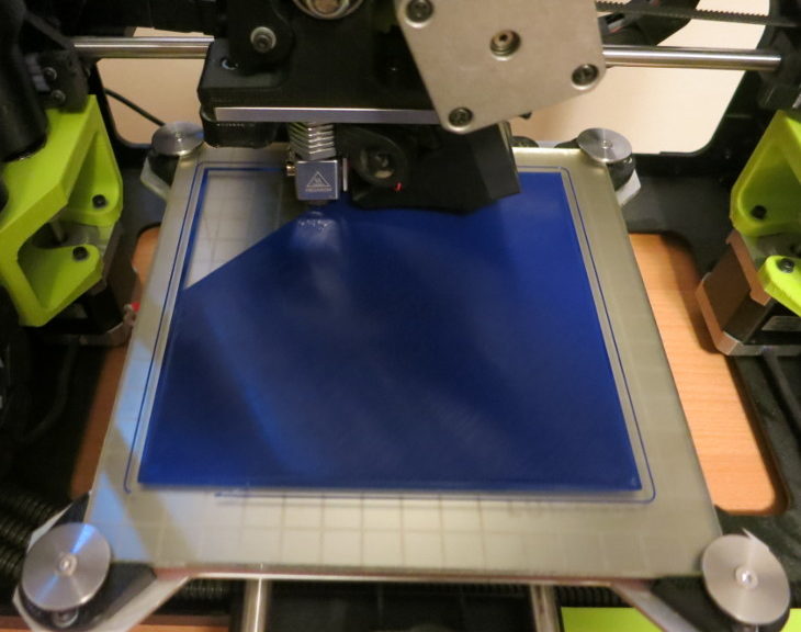
Once the rectangle started printing, I realized that this little test object is also a great way to look at the bed leveling and Z height over the whole printable surface, by flipping the printed rectangle over and looking at the uniformity of the first layer fill. Here things look… ok.
As you can see if you click on the image above, the first layer looks a little different in the back-left corner (lower-right in this picture) and front-right corner, which suggests the auto-leveling is a tiny bit off. That’s ok for now.
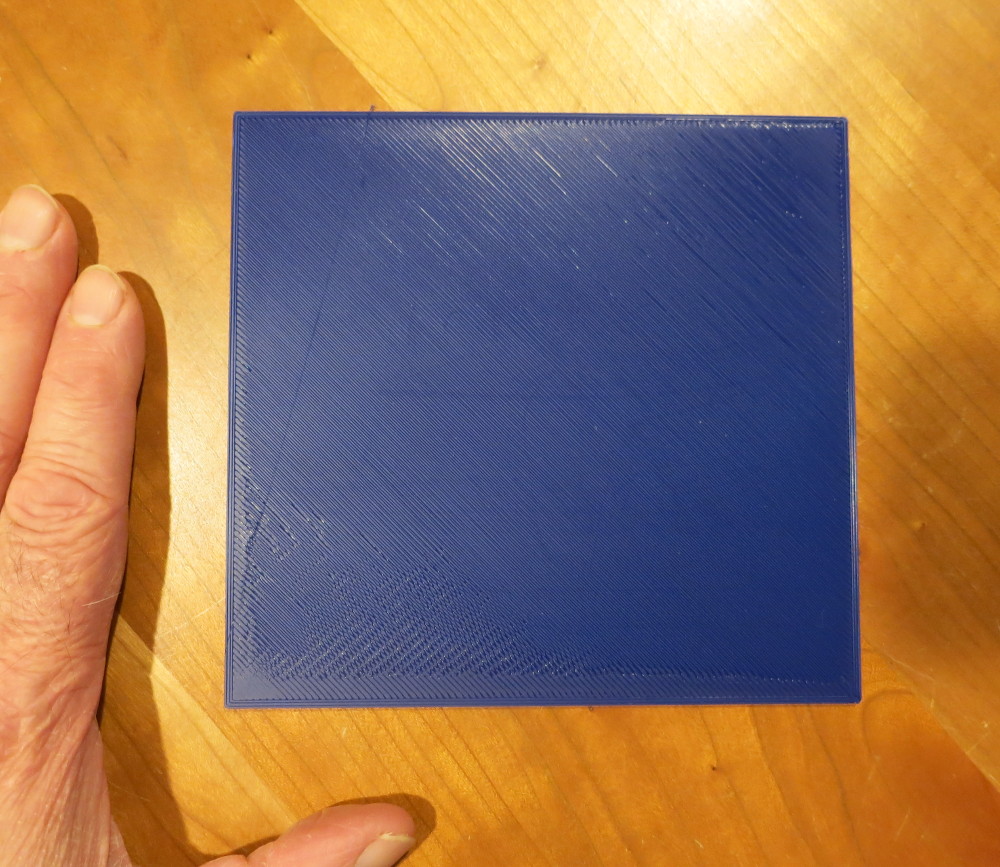
Looking at this rectangle, I realized it’s also a great test of absolute dimensional accuracy (if you print in a non-shrinking filament such as PLA). For example, my printed square measures 138.6 mm wide by 131.5 mm long; about 0.5 mm error in 138 mm, which is about 0.4% absolute error across the full print bed. Not bad at all.
So I now have a handy rectangular object I can print to test several things about my printer: 1) maximum print area, 2) First layer quality across the entire print bed, 3) absolute dimensional accuracy, 4) bed leveling.
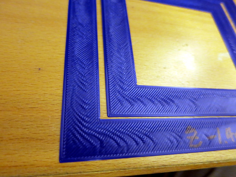
UPDATE September 1, 2018: I’ve created another test rectangle, that prints much more quickly, and is only one layer high. It’s a sort of picture frame, whose outer edges are as large as I can print, and whose inner edges are about 20 mm inside of the outer edges. That print shows the same differences in the corners of the bed as the first, but prints in about 25 minutes instead of over an hour.
The photo below shows part of the bottom of a test print with my Lulzbot Mini’s Z Offset set to -1.20. Notice how the lines of filament don’t merge at all. Also, this print of PLA barely stuck to the print bed because the filament isn’t squished into the bed much. This is a poor first layer.
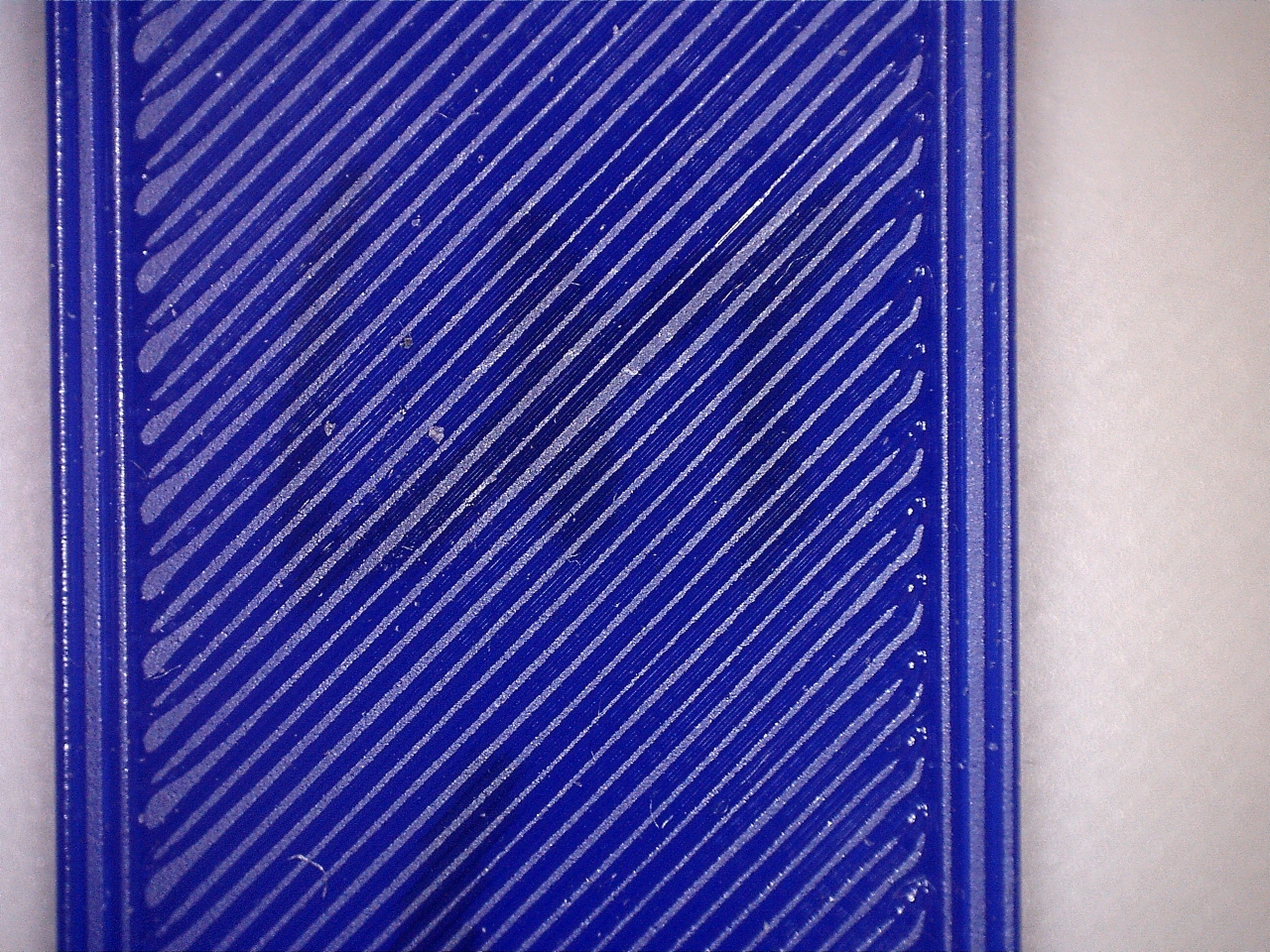
The next photo shows the same part of the same test print, printed with Z Offset set to -1.40. Notice how dramatically more merged the lines of filament are. There are two other hints that this Z Offset value is better: the filament looks more flattened (in fact a bit too much) in cross-section, and the print sticks to the bed far better.
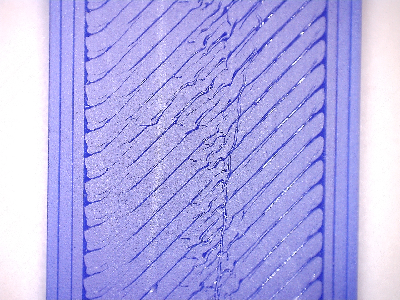
Next I’m going to fix a ripple that wasn’t visible when the first layer height was incorrect, but now shows up dramatically well. In the photo below I’ve overlapped two prints of the same ‘picture frame’ test print. You can see how they both show a similar ripple pattern.
The most likely cause (so I hear) is loose belts. See my next post, on extruder tension, to find the what turned out to be the problem.
All this handy diagnostic information was gained from one print model: a full-bed picture frame one layer thick.