
Now that my Dog Bed Weight Scale is sending data, I’m going to have a go at a water bowl scale. The idea is that, like the bed, the bowl will periodically send its weight to a cloud. This data should tell me when Pippa drinks, when we refill her bowl, and (maybe) how much she drinks.
The work-in-progress sources on Github, contain the beginnings of the Arduino 101 Sketch, Bill of Materials (Parts List), mechanical design/construction details, and a day-by-day project diary.
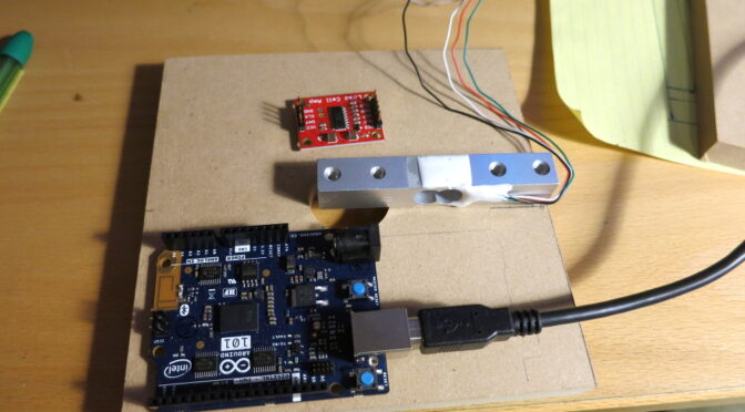
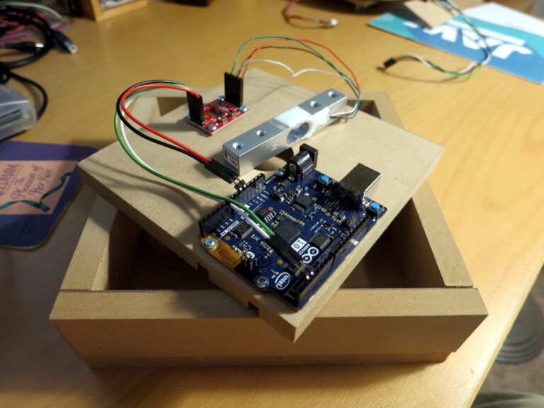
Since I was already familiar with Sparkfun’s Load Cell Amplifier, I only needed to pick a Load Sensor/Cell. I decided to go with their 10kg bar Load Cell because it should be easy to mount as a single-point weight sensor, and it’s relatively inexpensive.
I decided to construct the scale from 1/2-inch MDF (Medium Density Fiberboard) because it’s thick enough to minimize bending and it’s not too heavy. Although raw MDF swells and warps if you get it wet, that’s not a problem if you put a good coat of paint all over it – so I’ll be painting the parts before I assemble the whole scale.
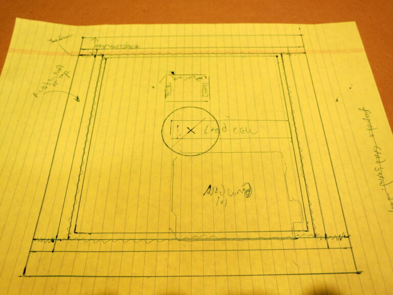
With the major parts chosen, I sketched the to-scale wooden parts and the layout of the electronic parts.
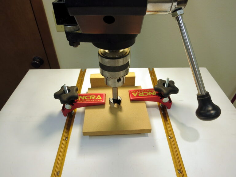
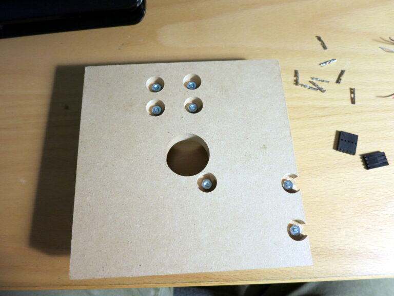
I then cut the MDF pieces and bored the access hole that will let me assemble the last of the parts.
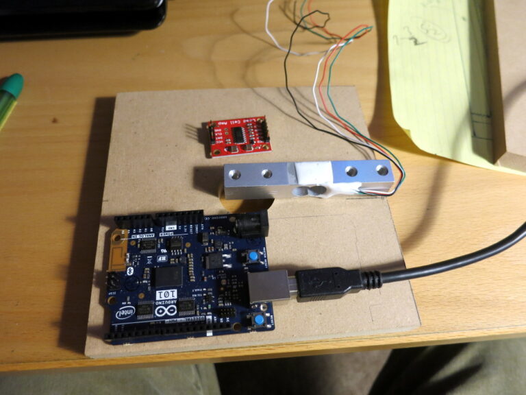
I then test-laid-out the parts on the bottom plate of the scale. Doing that reminded me that the assembled scale needs a way for a USB or power cable to get out of the scale. I decided to probably cut a diagonal channel in the bottom plate to allow for a cable – if I’d put the Arduino 101 where I initially planned to put it, the USB cable shroud would be in the way of the lid.
Note: the lid includes a water curtain on its sides, which needs to overlap with the edge of the bottom plate to keep spilled water from getting into the circuitry.
I then used a drill press to drill the holes for the mounting screws and counterbore the holes for the nuts on the bottom.
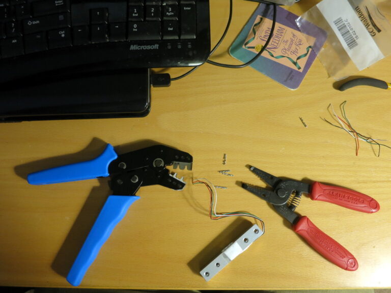
The next step was to make the connectors for the circuitry. I probably should have soldered thicker wires (an inch or so in length) to the Load Cell wires, because the Load Cell wires were too thin to crimp connectors onto – the Load Cell wires are very fragile.
Because there’s only one Load Cell, and because it connects directly to the Load Cell Amplifier (unlike the half-load-cell Load Sensors I used in the Bed Scale), the circuit is pretty simple.
I’ve ordered parts from McMaster-Carr to mount the Load Cell to the top and bottom of the scale. That mounting will look a lot like the Two Plate Configuration shown in Sparkfun’s Load Cell Amplifier Hookup Guide, except that my scale will have a lip fastened to the top plate to keep spilled water out of the electronics.
In my next post, I finish the woodworking… with some surprises.