
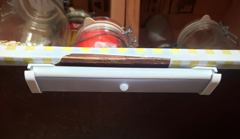
A while ago we bought rechargeable light bars for our pantry shelves, and we love them. The only problem was that because they were held to the underside of the shelf by weak magnets, every time we bumped a light or dropped a heavy jar into the pantry, the light would clatter to the floor.
This post covers my process of creating, in FreeCAD, clips that would hold the lights securely. I’m really pleased at how they turned out.
Requirements
I started with a list of requirements for the clips:
- Each light bar will be held in place by two clips, which screw into the underside of the shelf.
- The clips will hold the bar in place: no left-right movement or front-back movement.
- You should be able to pull the light bar forward, out of the clips, to plug the bar into a charger.
- As always, it would be nice if the print didn’t require support during printing. I find removing supports from a print is often a pain and leaves ugly edges.
- The clips fit the 3/4″ (19 mm) flat-head screws that I have lying around.
How the Design Developed
The light bar shape is basically an extruded end profile. Because that profile is not rectangular, I wanted to create a Sketch in FreeCAD of the end of the light bar.
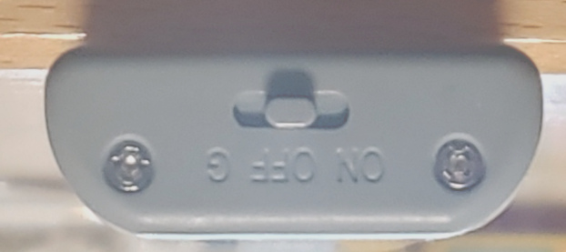
I laid a light bar on my office desk, the end facing toward me, then took a photo of that end. I made sure to be reasonably centered on the end, and held the camera far enough away from the end to avoid distortion.
I then cropped that photo down to just the end of the light bar, then flipped it upside-down so it would be oriented like the light will be when it’s fastened to the underside of a shelf.
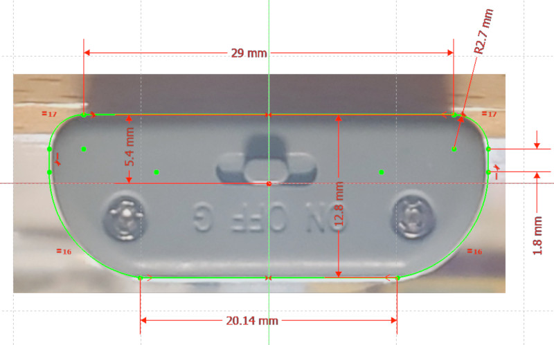
Since FreeCAD version 0.19, it’s been easy to use the Image Workbench to import a photo and calibrate its width by measuring the distance between two points in the real thing. I measured the width of the end of the light bar, marked the two sides of the light bar in the photo, then entered the measurement.
Using the now to-scale photo, I created a Sketch to match the outside edge of the end of the light bar.
I didn’t have any luck drawing a sketch of the clip on paper, so I just started experimenting with elements to fit the requirements: A horizontal tab with a hole for a screw; a flexible hook to enable the bar to be removed easily; an end-stop of some sort to keep the bar from sliding left-right.
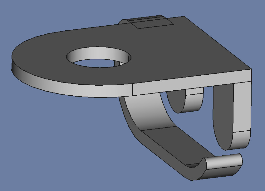
After a bit of experimentation I had a first version.
I immediately saw one thing to fix: I want the clip to print without Supports, but no matter how I oriented this clip, it would require supports for either the two lobes of the end stop or the hook.
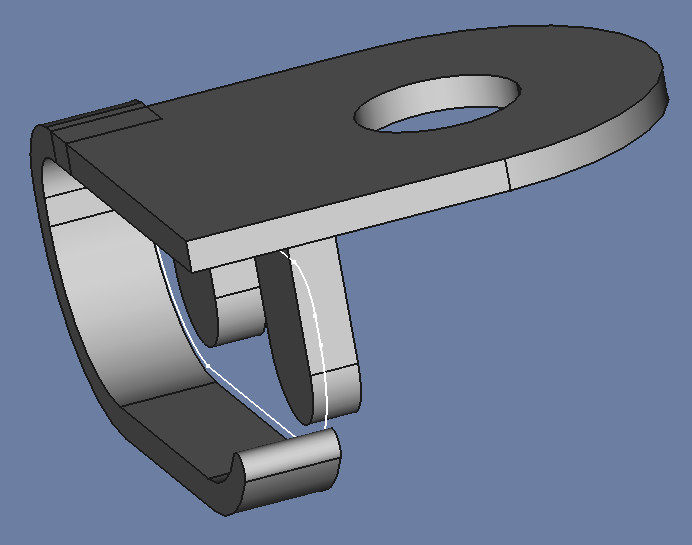
After staring at the design in FreeCAD I had an insight: If I reversed the screw-tab to point inward instead of outward, I had a chance of making the clip print without supports. First I simply reversed the direction of the tab that held the screw.
…then I saw that I could widen the hook to be even with the right side of the end-stop, print the clip on its right side (rotated 90°) and eliminate most of the support. I could then change the round screw hole to have a point and eliminate the need for support for the screw hole.
I was happy enough with the result that I did a test print to check dimensions and fit.
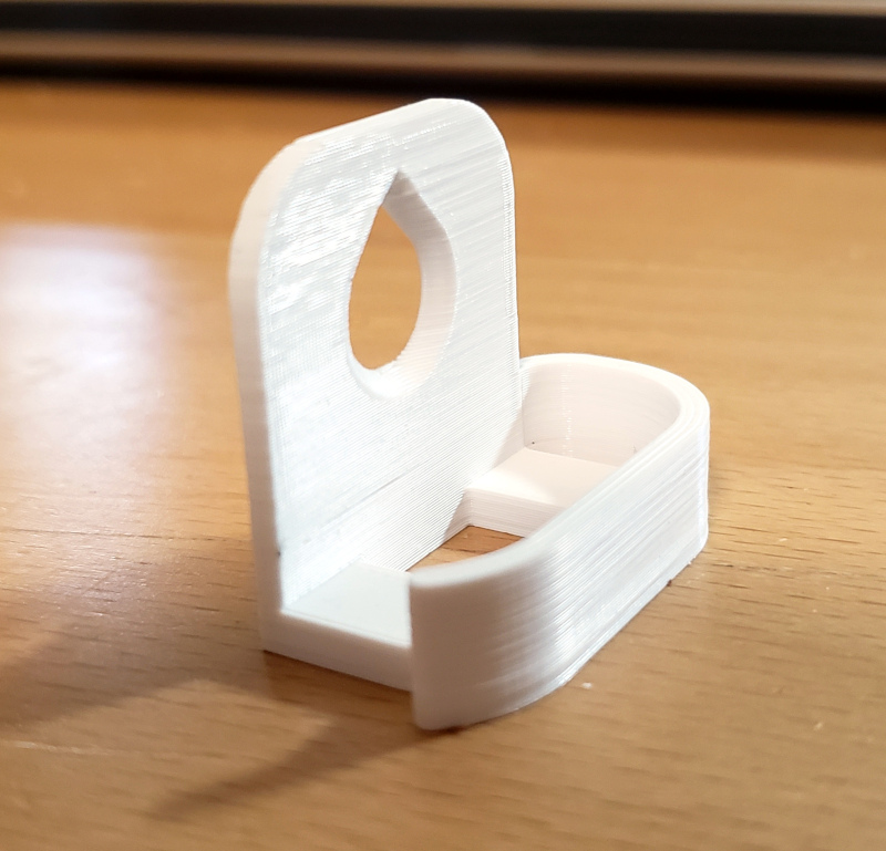
The printed clip fit the lamp bar well enough, but needed a few adjustments:
- I reduced the height of the hook by 1 mm to fit the lamp bar better.
- I made the end of the hook curl up further (60° instead of 50°) to make it less likely the lamp would fall out.
- I made the screw hole fit the flat-head screws I wanted to use, by making the screw tab 4 mm thick, with a 3 mm chamfer.
- Doh! I had made the old radius vs. diameter mistake, making the screw hole twice as large as it should be. I changed the screw hole from a 4.5 mm radius to a 2.25 mm radius.
The second print looked much more promising.
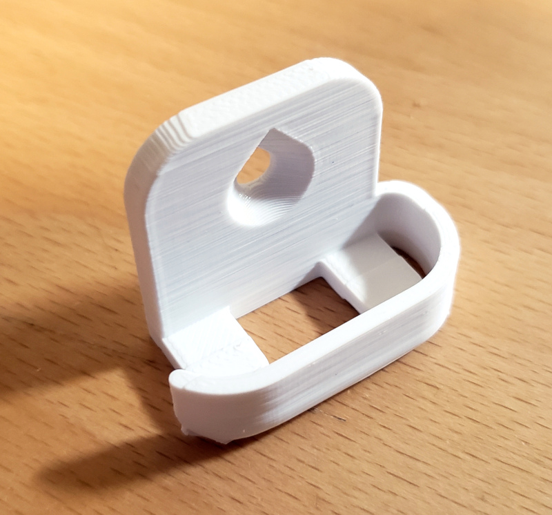
Now that everything fit, I could step back and look at the design again. I decided to replace the two end-stop tabs with a short bar and only one tab. That arrangement made it easier to remove and insert the lamp bar without the clip hanging up on the light’s switch.
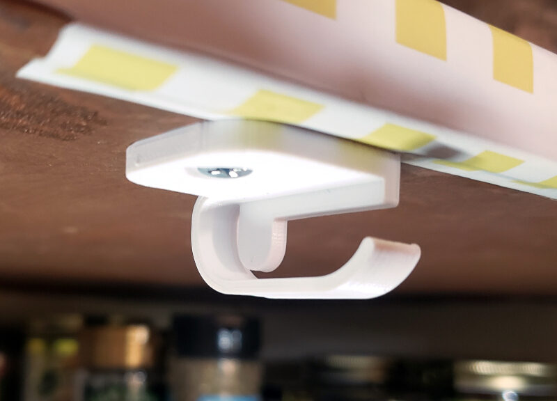
Success
This design worked well enough that I called it good. I printed a left and right version by mirroring in FreeCAD, then printed the 3 sets I needed to install all the lamp bars in the pantry.
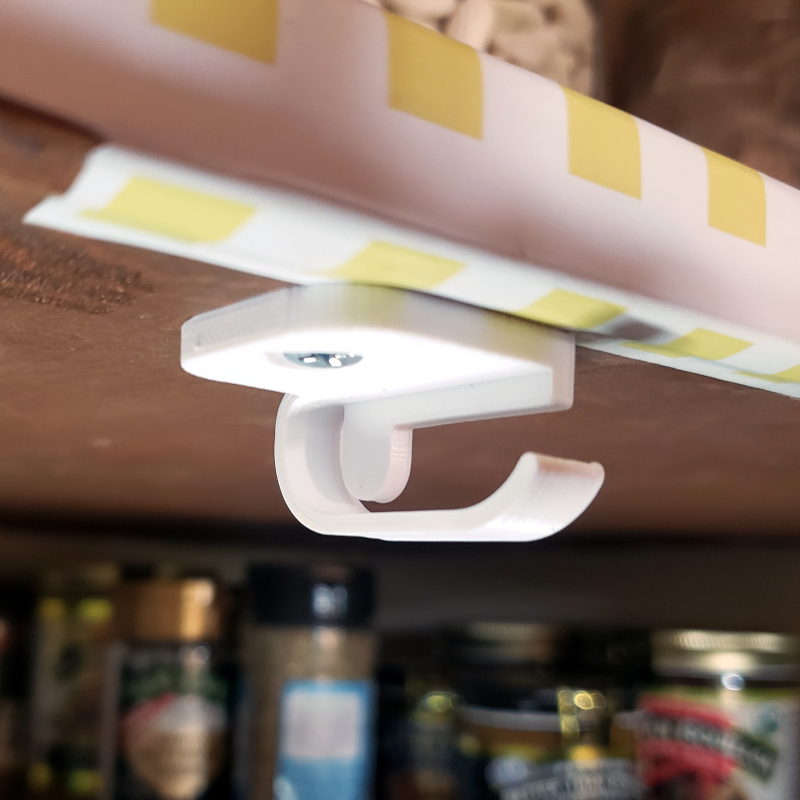
3D printing was, indeed, handy for designing and printing these household objects.
Join the conversation about this post on Mastodon.