
In an earlier post I calculated the ideal pendulum period for the Korean clock by counting its wheels’ teeth (outer teeth) and pinions (inner teeth). This post is an update based on the errors I made while attempting to do the same for my second clock: the Ansonia kitchen clock.
What follows is a more detailed “how to” for calculating the pendulum period based on gear ratios.
Disassembly
Cleaning a clock properly involves disassembling the clock and cleaning each part. As part of the disassembly process, take lots of photos of how the movement originally fit together and the relative position of all the parts in the strike train – so you can put the clock together again.
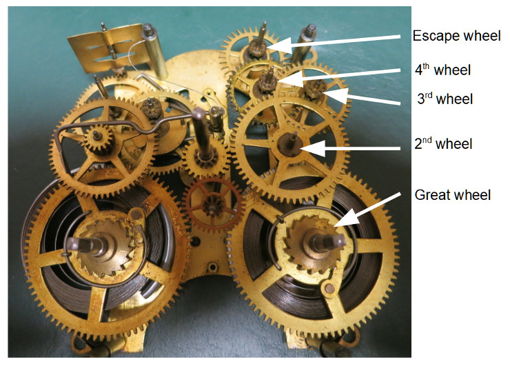
The photo above shows the Ansonia clock’s movement just after I removed the front (top) plate that holds the parts together.
The time train is the set of wheels (gears) connected to the escape wheel. You can find the escape wheel – the upper-right wheel in the above photo – because it has distinctive, pointed teeth.
Note which wheels connect the escape wheel to the mainspring; those wheels make up the Time Train. In the photo above, I’ve labeled those wheels: The great wheel is the mainspring gear; the 2nd, 3rd, and 4th wheels are numbered based on how they relate to the great wheel. The minute wheel or minute post is the shaft that turns the minute hand.
I didn’t label the Intermediate Wheel – the gear just below the minute wheel in the above photo – because it turns the hour hand, and isn’t involved in the calculation of the pendulum period.
Note the path from escape wheel to minute post
Now that you know which wheels are in the time train, note how the minute hand is – indirectly – connected to the escape wheel. How the minute hand is connected varies depending on the clock design. In some clocks the minute wheel is directly in the path from the mainspring to the escape wheel. In contrast, in this movement the minute wheel is not. That is, if you removed the minute wheel, you could still turn the escape wheel by turning the great wheel.
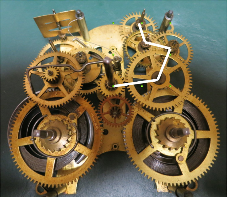
So, in this movement the path from the escape wheel to the minute wheel is: escape wheel, 4th wheel, 3rd wheel, 2nd wheel, minute wheel.
Count the wheels’ teeth and pinions
Once you’ve cleaned all the wheels, make a table of the number of teeth (outer teeth) and pinions (inner teeth) for each wheel. Accurately counting those teeth can be tricky, especially for large wheels – it’s easy to miss one or two teeth. I like to take a photo of each wheel, looking straight down onto the gear. These photos simplify counting the teeth, and are also handy for finding bent, worn, or broken teeth.
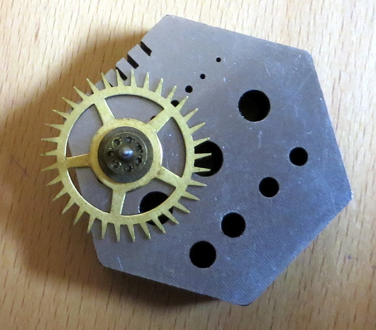
The photo above shows the escape wheel – note the long, pointed teeth . You can easily count the teeth in this photo – 34 – and the number of lantern pinions (the slots in the hub) – 7.
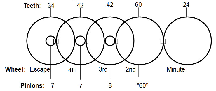
I took pictures of all the involved Time train wheels, counted the teeth and pinions in each wheel, and made the following list:
- Escape wheel: 34 teeth, 7 pinions
- 4th wheel: 42, 7
- 3th wheel: 42, 8
- 2nd wheel: 60, “60”
- Minute wheel: 24 (we ignore the number of minute wheel pinions because the aren’t involved in the path from minute wheel to escape wheel)
Because the minute wheel is driven by the outer teeth of the 2nd wheel instead of its pinions, I wrote “60” in quotes – the number of outer teeth – for the 2nd wheel number of pinions.
Calculating the pendulum periods per minute wheel turn
Now that we have all the numbers, we can easily calculate the number of pendulum periods (a tick + a tock) required to turn the minute hand one full turn (one hour).
Each pendulum period allows the escape wheel to turn forward one tooth. When the pendulum swings one way, the “tick” releases one tooth of the escape wheel and catches a different tooth on one side of the verge (the pallet, which is connected to the pendulum crutch). When the pendulum then swings the other way, the “tock” catches the tooth next to the first tooth of the escape wheel on the other side of the verge, and the pendulum is back where it started. See Wikipedia’s Anchor Escapement page for details.
Because the escape wheel has 34 teeth, it takes 34 pendulum periods to advance the escape wheel one full turn.
So how many pendulum periods does it take to turn the 4th wheel one full turn? Because the escape wheel has 7 pinions, and the 4th wheel must move 42 teeth to make one turn, the answer is 34 * (42 / 7) =, or 204 pendulum periods.
Skimming over some of the math, an easy way to calculate the number of pendulum periods required to turn the minute wheel one full turn is to multiply the number of teeth of each wheel involved, then divide that by the multiplied number of pinions of each wheel involved:
pendulum periods per full minute wheel turn = 34 * 42 * 42 * 60 * 24 / (7 * 7 * 8 * 60), which = 3,672.
Calculating seconds per pendulum period
The minute hand takes one hour to turn, so the minute wheel takes the same time to make one full turn. One hour is 60 minutes of 60 seconds each, so we can calculate pendulum periods per second by dividing the periods per minute wheel turn by the number of seconds per hour: 3,672 / (60 * 60) = 1.02
We want seconds per pendulum period rather than pendulum periods per second, so to find that we just take 1 / 1.02 = 0.98039215686274509803921568627451. For clock-setting purposes, we only care about this time rounded to the microsecond (6 decimal places), so the ideal pendulum period for this clock movement is 0.980392 seconds.
We’ll use this number in two ways during clock repair and restoration:
- If the pendulum is missing, we can calculate roughly how long the pendulum should be. See my post on Making Sense of the Time Gears.
- To save a lot of time in regulating the clock – setting the clock’s speed – we can record the time per pendulum period, and adjust the pendulum length accordingly – usually by turning a nut that the pendulum bob sits on, or turning a Fast/Slow post with a key. Measuring the pendulum period is a lot faster than measuring the minutes gained or lost once a week! For details, see my post on Adjusting the Korean clock speed.
About measuring the time the pendulum takes to swing, clock repairers often express the pendulum timing in BPH (Beats Per Hour), where a Beat is either a tick or a tock. We can calculate the ideal BPH for this clock by taking the calculated pendulum periods per second, multiplying by two, then multiplying by 60 * 60. We multiply by 2 because there are two beats (one tick plus one tock) per pendulum period; we multiply by 60 * 60 because an hour is 60 minutes of 60 seconds each. So the ideal BPH for this clock is 1.02 * 2 * 60 * 60 = 7,344 BPH.
By the way, another number that’s handy for regulating the clock is the ideal number of pendulum periods per week. You’ll use this number to calculate the minutes of time gained or lost each week based on the current, measured pendulum period.
The number of seconds per week is 60 seconds per minute times 60 minutes per hour times 24 hours per day times 7 days per week: 60 * 60 * 24*7 = 604800 seconds per week.
Divide that number by the seconds per ideal pendulum period to get the number of ideal pendulum periods per week: 604800 / 0.980392 = 616896.0 ideal pendulum periods per week.
To see how this number helps in regulating the clock, let’s assume we’ve measured the current clock pendulum period as 0.980497 seconds. Sounds pretty close to ideal, no? Let’s subtract it from the ideal period from it to see how much time (seconds) is gained or lost per pendulum period: 0.980392 – 0.980497 = -0.000105. That says this clock is currently losing about 100 microseconds per pendulum period. Still sounds pretty good.
Now we take that difference per ideal pendulum period and multiply it by the number of those pendulum periods per week: -0.000105 * 616896.0 = -64.77408, which is a little over a minute per week. Actually, that’s pretty good.
Notice that because this clock’s ideal pendulum period is about 1 second, a difference per period of 100 microseconds, or 0.0001 seconds means gaining or losing about 1 minute per week.
So we have a handy rule of thumb: For an about 1 second pendulum period, each 0.0001 second difference from the ideal pendulum period will produce about 1 minute of error per week.
So for example, if you measure the pendulum’s current period at 0.980,792 seconds, you can easily see that the clock will lose about 4 minutes per week (0.980392 – 0.980792 = -0.0004 seconds; -0.0004 / 0.0001= -4).
Practically speaking, if your 20th-century spring-driven clock gains or loses only 1 minute per week, it’s doing pretty well. So you should call it good if you can adjust your clock’s pendulum’s period to within 0.0001 seconds of the ideal you calculated.