
In my previous post I found the center of gravity of the top plywood circle of the Dog Bed Weight Scale. This post goes through the math of calculating the weight W on the scale and the position {X, Y} of that weight’s center of gravity. That is, how much does our dog PIppa weigh when resting on the bed, and what is her position on the bed?
The physics of levers says two things about a “Class 1 Lever” (a seesaw):
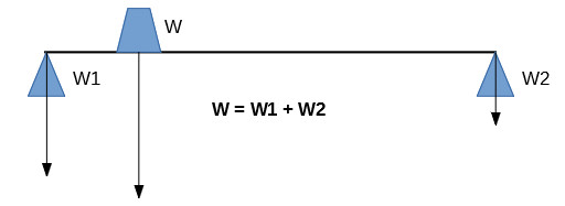
- The weight experienced by the fulcrum (W) must equal the weights placed on the seesaw (W1 and W2). If this were not true, the seesaw would sink into the ground or fly into the air.
- The Moments (rotational force) around the fulcrum must sum to zero. If this weren’t true, the seesaw would tip.
So calculating W, the weight of the Dog (Pippa!) is easy. It’s the sum of the weight sensed by each of the four Load Sensors:
W = A + B + C + D
Calculating the {X, Y} of the weight’s center of gravity takes a little math. We’ve already said that A, B, C, and D are the weights sensed by the four Load Sensors. In the figure below, U and V are the dimensions of the scale (the rectangle formed by the four Load Sensors), X and Y are the to-be-calculated position of the weight’s center of gravity.
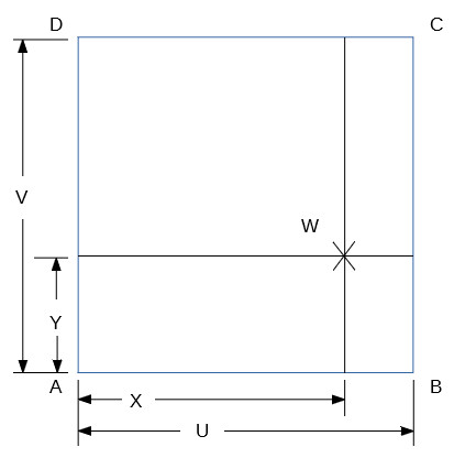
To calculate X and Y, we use a property of the center of gravity: that for any line going through the center of gravity, the sum of the Moments on one side of the line balance (equal) the sum of those on the other side of the line.
Imagine a knife-edged fulcrum runs all the way under the line PQ. Because PQ goes through the center of gravity, the Moments perpendicular to that line segment must sum to zero.
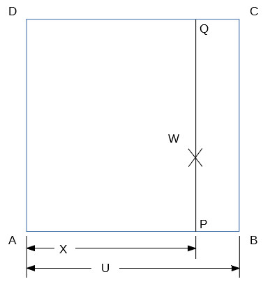
AX + DX = C(U-X) + B(U-X)
so
AX + BX + CX + DX = CU + BU
so
X = (C + B) / (A + B + C + D) * U
We calculate Y in the same way we calculated X:
Imagine a knife-edged fulcrum runs the length under the line RS. Because RS goes through the center of gravity, the Moments perpendicular to that line segment must sum to zero.
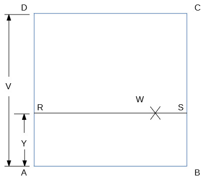
AY + BY = C(V-Y) + D(V-Y)
so
AY + BY + CY + DY = CU + DU
so
Y = (C + D) / (A + B + C + D) * V
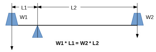
We’re not quite done: What we’ve calculated is the center of gravity and weight of everything on the scale: the top plywood circle, the bed, bedclothes, and the dog. In the figure below, suppose T is the weight of the Top plywood circle, bed, and bedclothes, W is the measured weight, and P is the to-be-calculated position and weight of the dog, Pippa.
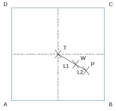
We have to do one more lever calculation: Imagine a fulcrum at W. Because of the laws of levers:
T * L1 = P * L2
W = T + P
We know T (weight of plywood top, bed, bedclothes) from calibration. Pippa’s weight, P, is just
P = W – T
Further, we know the position of W from the calculations above. From the position of W we calculate the distance, L1, from the location of T to the location of W, by the distance calculation.
(Oops. I see a mistake here: This calculation assumes the center of gravity of the combined plywood top, bed, and bedclothes is the center of the scale. That isn’t true: the bedclothes will move around during the night, as Pippa tugs at them from time to time. So the center of gravity, T, is an unknown.)
L1 = sqrt((X – (U / 2))^2 + ,(Y – (V/2))^2)
Now that we know T, L1, and P, we can calculate L2:
L2 = T * L1 / P
From there we can use vector addition to calculate the X and Y of Pippa’s center of gravity.
In my next post, I set up the first of the four Load Sensor plus Load Cell Amplifier combinations.
May 1 update: I did a search that I should have done when I started the project: “load sensor center of gravity”, and found a nice formula from Loadstar Sensors, who make commercial products to measure center of gravity. Incidentally, they make products that measure your dynamic center of gravity (like happens in a golf swing) – which is pretty impressive. Anyway, their formula for center of gravity is
X = (W1X1 + W2X2 + W3X3 + W4X4) / (W1 + W2 +W3 +W4)
Translating into our terminology, W1 = A, W2 = B, W3 = C, W4 = D and X1 = 0, X2 = U, X3 = U, X4 = 0.
so
X = (0 + BU + CU + 0) / (A + B + C + D)
so
X = U (B + C) / (A + B + C + D)
Which is equivalent to our formula of
X = (C + B) / (A + B + C + D) * U
Finding that page gives me a lot more confidence that our center of gravity calculation is correct.