
In my previous post, I worked through the calculations of weight and center of gravity when using four Load Cell Amplifiers instead of one. In this post, I build the circuit for the first of the four Load Sensor / Load Cell Amplifier combinations I’ll be using.
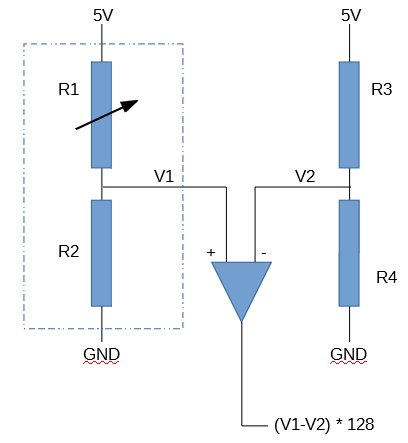
The Sparkfun Load Cell Amplifier is designed to connect a Load Cell to an Arduino. A Load Cell contains a full (4 resistor) Wheatstone Bridge, but a Load Sensor contains only half of a Wheatstone bridge. To connect a Load Sensor to a Load Cell Amplifier, I need to add two resistors: R3 and R4 in the following diagram. The dotted box represents the Load Sensor. The triangle in the middle of the diagram represents the Load Cell Amplifier. As the weight on the Load Sensor increases, R1 decreases, which causes the voltage V1 to increase, causing the digitized amplifier output to increase.
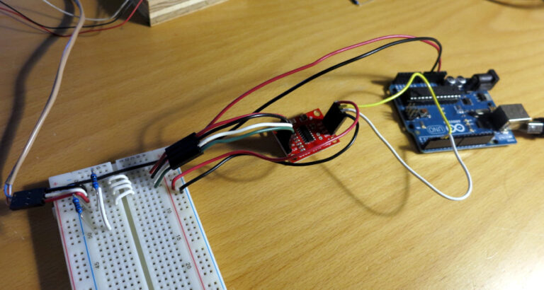
Once I’d built the circuit, the next task was to find the right pair of resistors, R3 and R4. In the photo below, R3 and R4 are the two resistors at the left; the Load Cell Amplifier is the small red board in the center, and of course the Arduino is on the right.
R3 and R4 need to have a ratio that is close to the ratio of the two (matched) resistors that are in the corresponding Load Sensor, so that the digitized voltage difference, V1 and V2 in the above schematic, is near zero.
The tricky part is that a normal multimeter shows that the two resistors of the Load Sensor are equal, and that R1, above, changes by only an ohm or so with pressure. That multimeter isn’t accurate enough to show the differences in resistance that you need to measure.
So either you can buy a high-precision multimeter (expensive), or you can use the Load Cell Amplifier to measure the resistances. I decided the use the Amplifier.
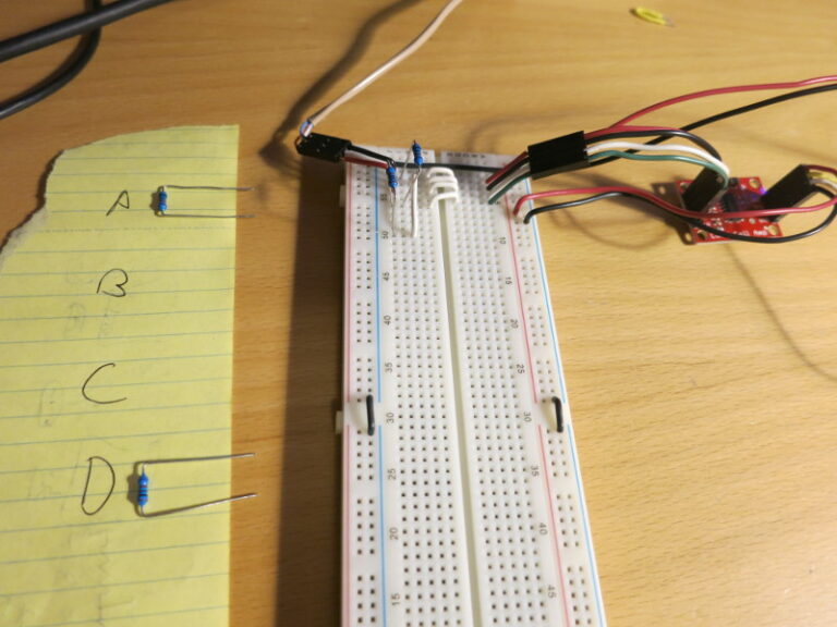
I ordered a bunch of 1Kohm, 0.1% resistors. Then I picked 4 of them (I could have used more, but that’s more work), labeled them A, B, C, and D, then started measuring the Arduino ADC (Analog Digital Converter) values of various pairings of those resistors.
First I removed the two resistors and connected S+ to S-, (V1 to V2 in the schematic above) to give the ADC a 0V input value. I then measured the ADC output. It was 5720, so 5720 corresponds to 0V difference between V1 and V2 in the schematic above. That number is the 0V goal: I want to choose a pair of resistors that produces an ADC value that’s closest to 0V.
So I disconnected V1 from V2, plugged in a pair of resistors (say, A = R3 and B = R4) and read the raw value from the HX711 library, via hx711.read().
After a few tests I found that C = R3 and D = R4 produced an ADC value of -29993. That value was the one that was a) negative and b) closest to the 0V value of 5720. Even though -29,993 is much bigger (in absolute value) than 5,720, the other combinations produced values 10 times that of the C and D combination.
I wanted a negative number, to give more range for the Load Sensor. As the weight on the Load Sensor increases, the voltage read by the Load Sensor Amplifier increases, so starting from a slightly negative voltage gives the amplifier more range than if you started from a slightly positive voltage. I’m still not quite sure whether the ideal zero-weight offset would be 0V, or some slightly negative voltage.
In my next post, I show the progress of the circuit so far, show how to use Long Break-Away Headers, and start transferring the circuit to a soldered protoboard.