
In my previous post, I designed and printed a Centering Guide to line up the top and bottom pieces of the scale. In this post, I finish assembling the scale.
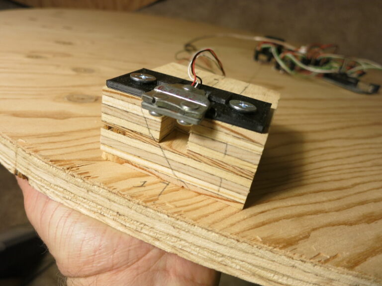
Now that I have the Load Sensor Holders that I designed and printed, I drilled mounting holes in the blocks that will hold the Load Sensors.
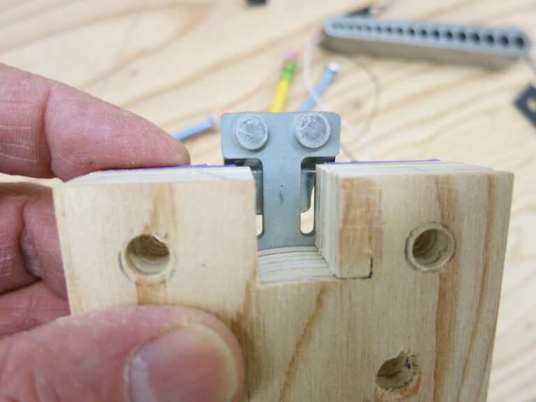
(I used only the two front holes you see in the picture; not the other hole)
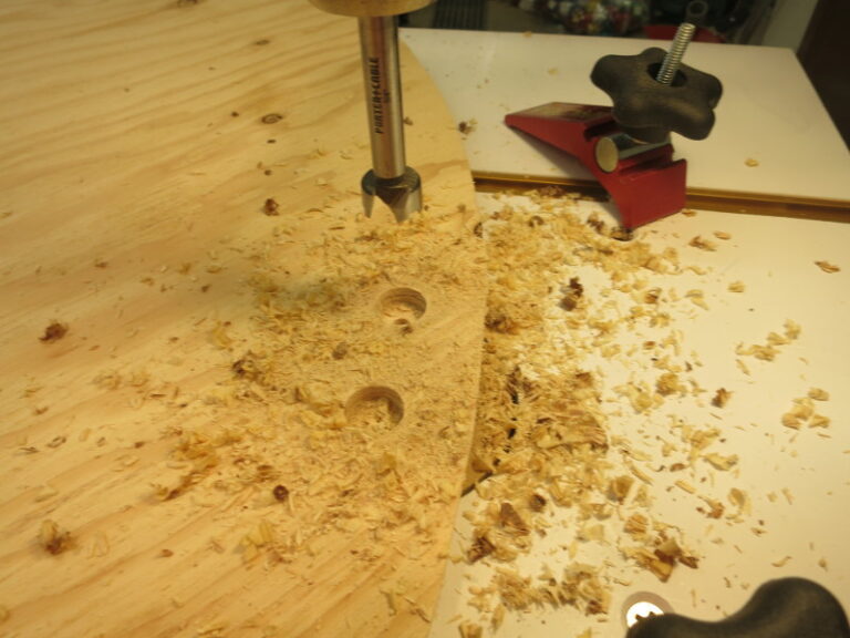
From there I lined up the support blocks on the bottom plywood circle, used a hand drill to extend the mounting holes through that part, then used a drill press and Forstner bit (on the bottom side of the plywood circle) to counterbore the holes that will hold the nuts that hold the bolts down.
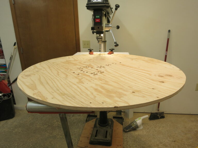
Note in the above picture that I’m using a support stand to hold the large plywood disk while I drill using the drill press. The support stand looks like a roller on a vertical bar. It’s a safety thing, to keep the plywood from crashing to the ground at the wrong time.
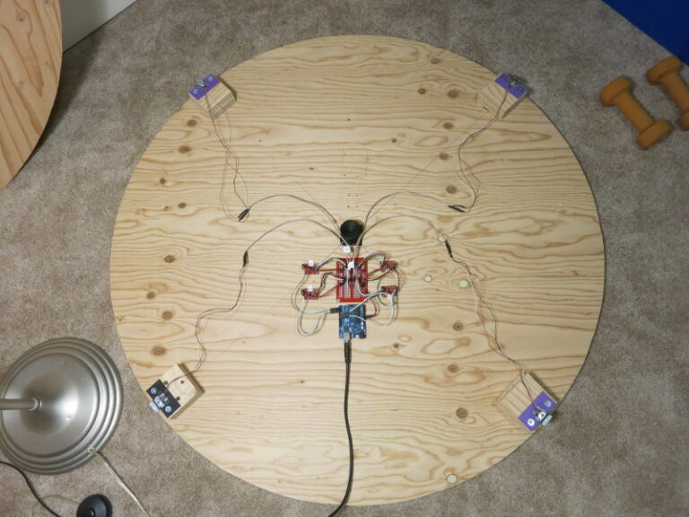
Once that was done it was an easy matter to line up each Load Sensor with the support blocks below it, slip the bolts through, and fasten them with the nuts.
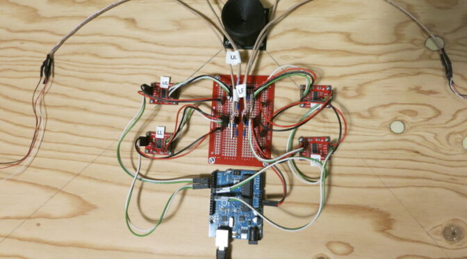
After mounting the Load Sensors, I mounted and connected all the other parts: the Arduino, Load Cell Amplifiers, Protoboard with resistors on it, and the plastic Centering Guide.
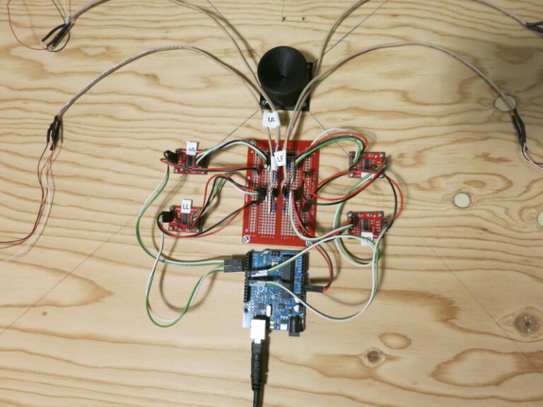
Finally, here is the long-awaited, assembled version 2 Dog Bed Weight Scale, ready to be calibrated. It contains 4 Load Sensors, a pair of resistors per Load Sensor to change the Load Sensor into a Wheatstone Bridge, a Load Cell Amplifier per Load Sensor to measure the weight on each Load Sensor, and an Arduino to make sense of it all.
In my next post, I’ll describe the Raspberry Pi code to transfer data from the scale to the cloud.