
It’s a good time to recap: This project is a scale that will sit underneath my dog Pippa’s bed, so that I can measure her weight automatically, at night while she sleeps. The project-in-progress is Open Source, at my CurieBLEWeightMonitor Github repository.
In my previous post I covered how to choose matching resistors for the Load Sensor to convert the Load Sensor into a Load Cell that can be wired into Sparkfun’s Load Cell Amplifier. In this post, I nearly finish building the breadboarded circuit and start transferring it to a soldered protoboard.
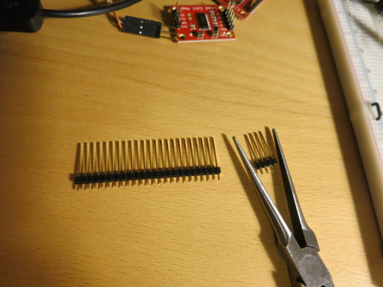
It’s probably worth saying a word about Long Break-Away Headers. These headers are longer than regular ones, and are great for plugging connectors into connectors and (for this project) plugging connectors into a solderless breadboard. Standard length headers are designed to be soldered in, and aren’t long enough to use in solderless breadboards or to attach connectors to Arduino I/O pins.
Step 1: snap off the number of pins you need for the connector. For example, I’m using a bunch of 4-pin Molex connectors, so I use a pair of needle-nose pliers to snap off a set of 4 pins.
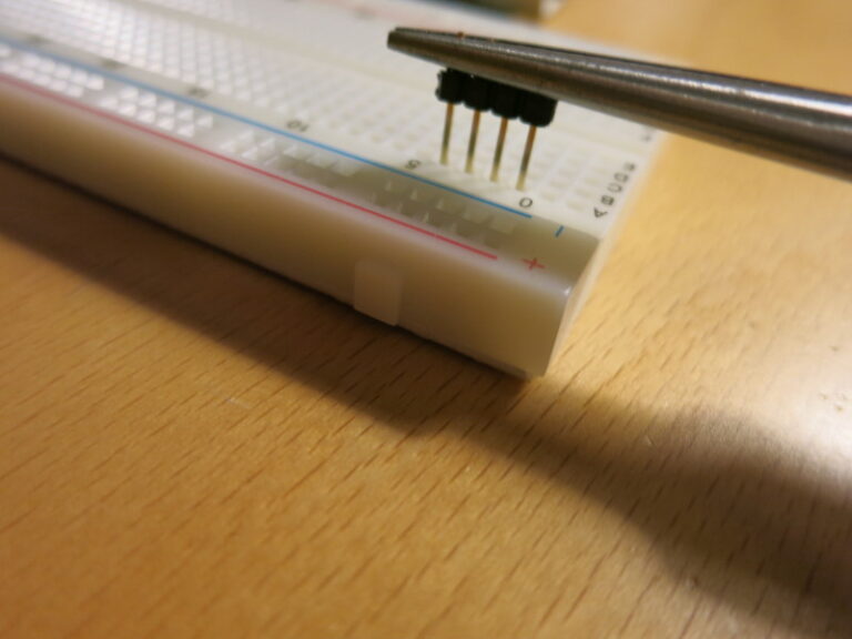
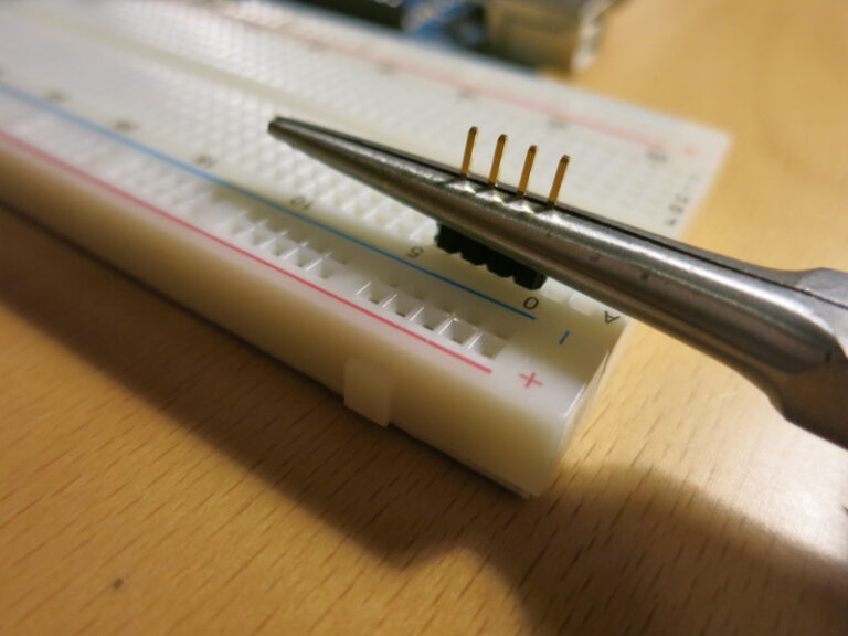
Step 2: The plastic separator needs to be centered on the length of the pins. An easy way to do this is to plug the long ends of the pins into a breadboard, then use needle-nose pliers to press the plastic part down to the surface of the breadboard. The plastic is often stiff, so I hold the pliers with one hand and press the tip of the pliers down with my thumb, using strong, even pressure (don’t bend the pins).
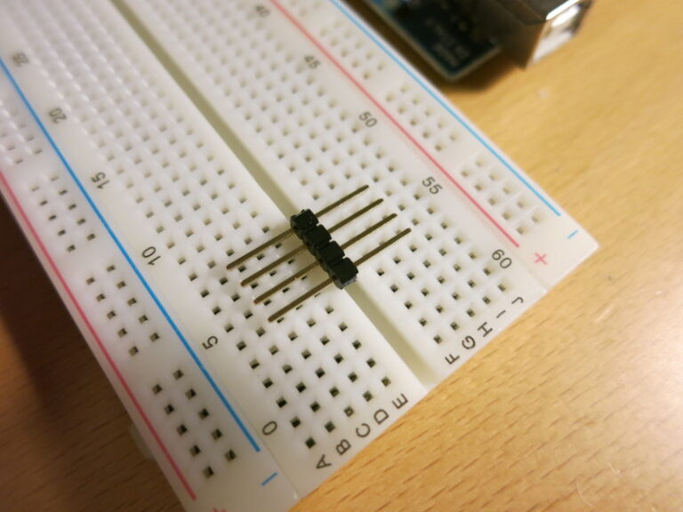
Once this is done, the header’s plastic separator is close to half way along the length of the connector, and the pins are ready to be plugged into a connector.
Meanwhile, I’ve finished everything on the breadboarded scale circuit except choosing the final pair of matching resistors. It’s all going well. In the picture below you can see the four Load Cell Amplifier boards (the small rectangular boards), the 3-pin connectors for each of the Load Sensors, and of course, the Arduino.
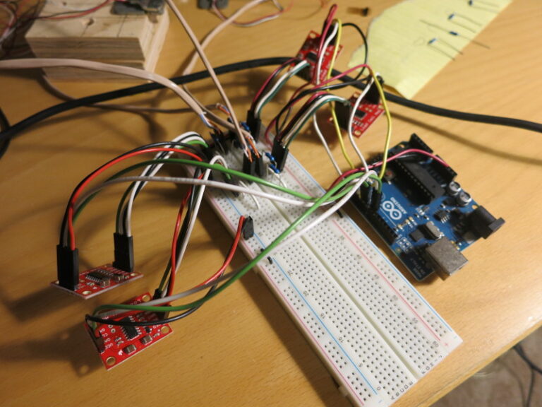
Earlier I’d noticed that the breadboarded circuit tends to drift: small changes in the mechanics of the circuit (like touching a resistor) make significant changes in the measured Load Cell Amplifiers’ outputs, which might affect the measured weight from the scale.
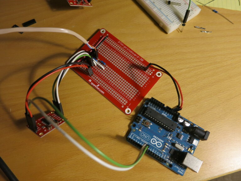
I found Sparkfun sells the perfect thing for me: a solderable breadboard. It has the same mechanical layout and electrical connections as a standard half-sized solderless breadboard, So it’s easy to transfer a circuit from a breadboard to the protoboard, and solder all the parts down. It’s especially nice for me because my protoboard connection skills are terrible: my protoboard circuits usually look like a mess, and are very difficult for me to wire up.
At any rate, I’ve transferred the first Load Sensor circuit to the protoboard and soldered it together – it works great!
In my next post, I solder the rest of the scale circuit to the protoboard and test-mount it onto the plywood base.