
In my previous post I described how to use long break-away headers, and started soldering the circuit together. In this post I finish transferring the scale circuit from the breadboard to a protoboard, and do a quick test mount of the circuit on the plywood scale base.
A reminder: I found that the Load Cell Amplifier was (by design) so sensitive to changes in resistance that just touching the resistors on my solderless breadboard caused large changes in the Amplifier output. So I wanted to solder all the parts down.
I’m generally terrible at soldering on protoboards, so I tried out one of Sparkfun’s Solder-able Breadboards. This board has internal connections that copy those of a solderless breadboard, making it easy to transfer your circuit from a solderless breadboard to this Solder-able Breadboard, without redesigning the layout and without having to solder two wires together – everything is soldering one wire into one hole.
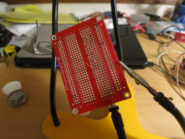
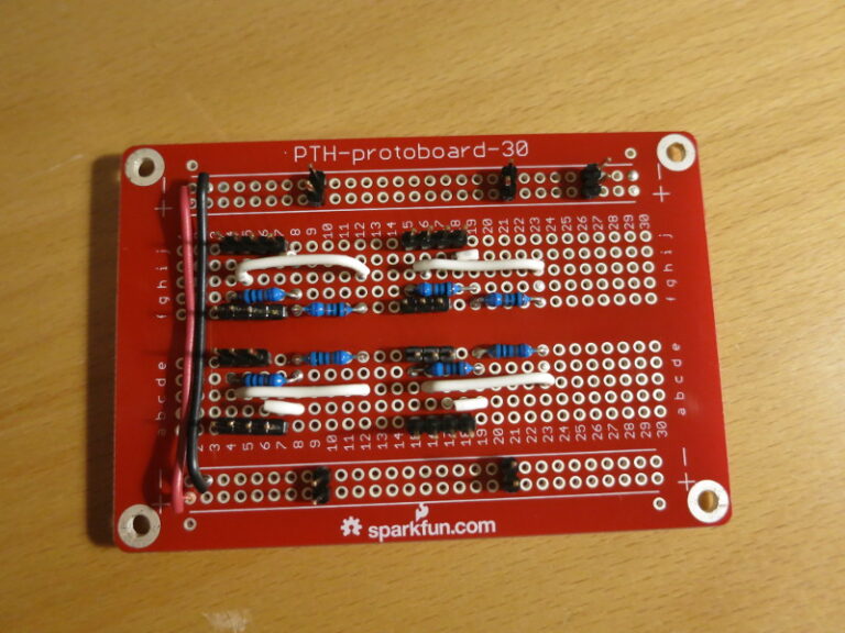
In almost no time, I had transferred the half Wheatstone bridge per Load Sensor to the board, and soldered the wires, resistors, Load Sensor connectors, and Load Cell Amplifier connectors in place.
Once I had everything soldered together, I plugged in the whole circuit and (temporarily – that’s another story) mounted the parts to the plywood bottom part of the scale.
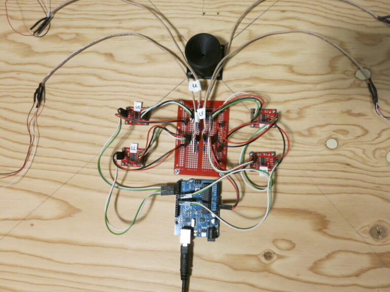
You can see in the above circuit the four Load Cell Amplifier boards (the small red boards) one per Load Sensor, the protoboard in the center, and the Arduino. Each Load Sensor is also plugged into the protoboard. Compare this picture to the one of the solderless breadboard in my previous post – it’s very, very similar.
In my next post, I 3d-print a Load Sensor holder.