It’s a good time to recap: This project is a scale that will sit underneath my dog Pippa’s bed, so that I can measure her weight automatically, at night while she sleeps. The project-in-progress is Open Source, at my CurieBLEWeightMonitor Github repository.
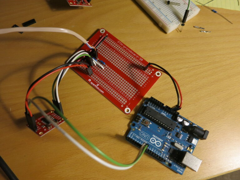
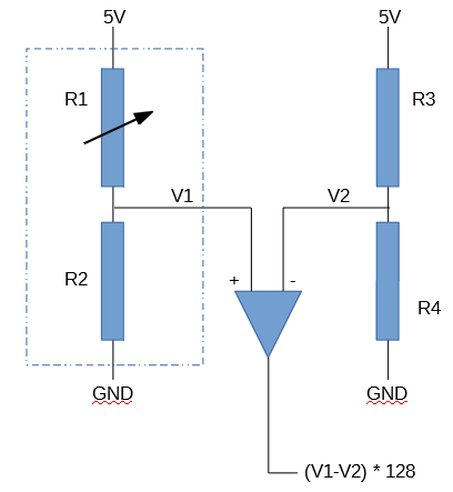
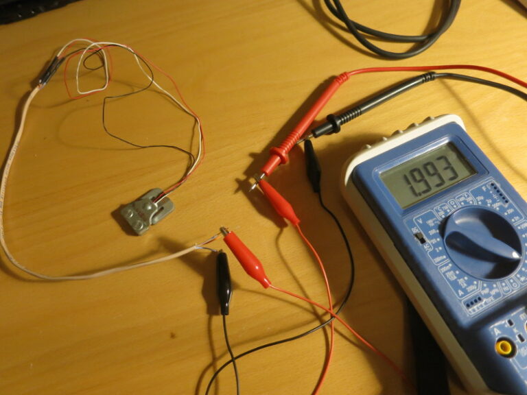
In my previous post I covered how to choose matching resistors for the Load Sensor to convert the Load Sensor into a Load Cell that can be wired into Sparkfun’s Load Cell Amplifier. In this post, I nearly finish building the breadboarded circuit and start transferring it to a soldered protoboard.
In my previous post, I worked through the calculations of weight and center of gravity when using four Load Cell Amplifiers instead of one. In this post, I build the circuit for the first of the four Load Sensor / Load Cell Amplifier combinations I’ll be using.
In my previous post I finished assembling the Dog Bed Weight Scale, at least enough to allow testing it. In this post, I relate how I calibrated and tested it.
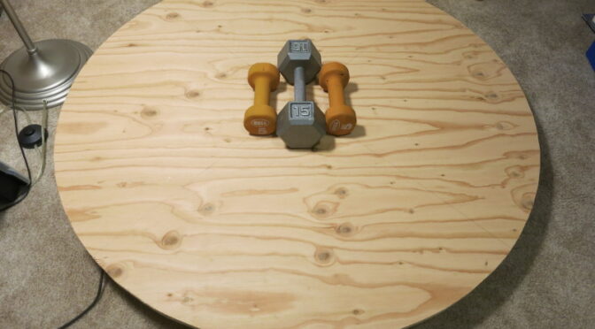
In my previous post I described the electronics of the Dog Bed Weight Scale. In this post, I’m doing the final woodworking and assembly – at least enough assembly to test the thing.
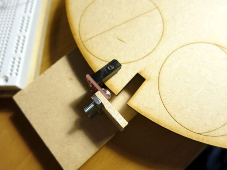
I’ve been doing a bit of mechanical work on the lunar clock, that I started in my previous post.
As a prototype to help me design the laser-cut parts, I cut out a strip of 1/8″ MDF, cut a square for the motor’s shaft and two holes for the motor mounting holes, then mounted the motor to that strip of wood.
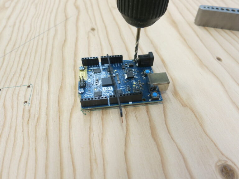
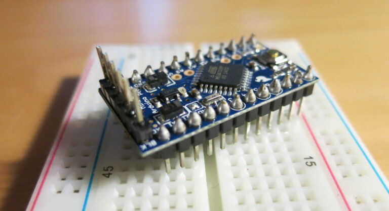
I recently decided to try out the Sparkfun Arduino Pro Mini 5V board. It has almost all the I/O that an Arduino Uno has, in a much smaller board. It comes without connectors, so you can solder in whatever style connector you need. For my uses, I needed to solder on male headers that allow it to plug into a breadboard.
So I tried out a new way of soldering male header pins onto a board. First I snapped off two 12-long headers from a strip of break-away male headers. Then I plugged those headers into a breadboard and laid the Arduino Pro Mini board over them. To keep the flux and solder spatter from getting into the breadboard holes, I put a piece of paper over the unused parts of the breadboard.
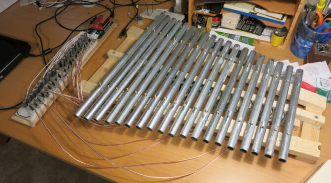
In my previous post I pointed to some sources of information about how to read Midi music files. I’ve now Open Sourced my working code.
I’m a total newbie at Git, but even so I’ve managed to create repositories for the Robotic Glockenspiel and the Arduino Midi File Reader library it uses. See My GitHub repositories for the current state of things.