
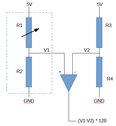
In my previous post, I worked through the calculations of weight and center of gravity when using four Load Cell Amplifiers instead of one. In this post, I build the circuit for the first of the four Load Sensor / Load Cell Amplifier combinations I’ll be using.
Continue reading Dog Weight Scale Part 7: Choosing Matching ResistorsTag Archives: Maker
Dog Weight Scale Part 6: Calculating the Dog’s Weight and Position
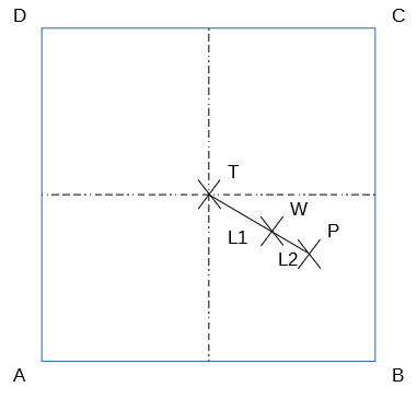
In my previous post I found the center of gravity of the top plywood circle of the Dog Bed Weight Scale. This post goes through the math of calculating the weight W on the scale and the position {X, Y} of that weight’s center of gravity. That is, how much does our dog PIppa weigh when resting on the bed, and what is her position on the bed?
Continue reading Dog Weight Scale Part 6: Calculating the Dog’s Weight and Position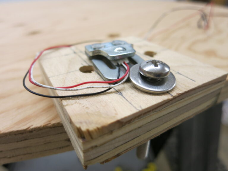
Dog Weight Scale Part 5: Center of Gravity and a Mounting Fail
In my previous post I described how to calibrate a load sensor. This post shows how to measure center of gravity, and shows a failed attempt to mount the load sensors to the scale.
Now that I’m using 4 load cell amplifiers rather than 1, I can calibrate each load sensor separately. This in turn will let the Arduino calculate Pippa’s real weight accurately regardless of what part of her bed/scale she’s lying on.
Continue reading Dog Weight Scale Part 5: Center of Gravity and a Mounting Fail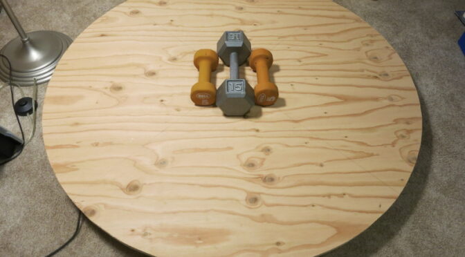
Dog Weight Scale Part 4: Calibration and its Difficulties
In my previous post I finished assembling the Dog Bed Weight Scale, at least enough to allow testing it. In this post, I relate how I calibrated and tested it.
Using the Bogde HX711 Load Cell Amplifier library and examples, and the Sparkfun HX711 Example Arduino Sketches, I quickly wrote a little Sketch to output the raw value from the scale (SCALE = 1.0 and OFFSET = 0L). The library made talking to the HX711 trivial.
Continue reading Dog Weight Scale Part 4: Calibration and its Difficulties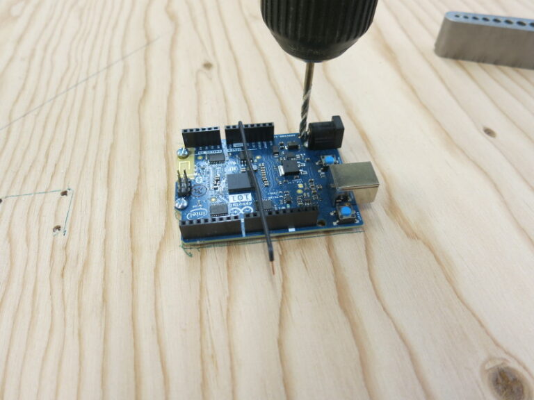
Dog Weight Scale Part 3: the Woodworking and Assembly
In my previous post I described the electronics of the Dog Bed Weight Scale. In this post, I’m doing the final woodworking and assembly – at least enough assembly to test the thing.
Continue reading Dog Weight Scale Part 3: the Woodworking and Assembly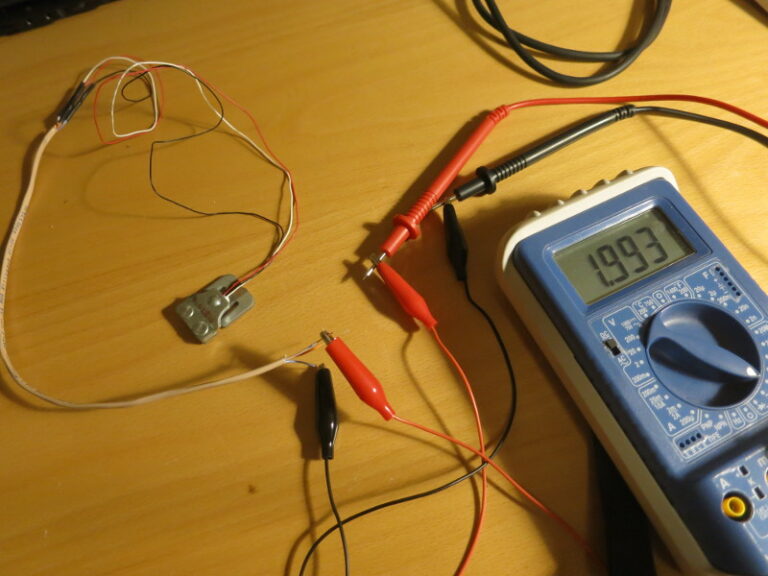
Dog Weight Scale, Part 2: the Electronics
As I said in the previous post, I’m using 4 Sparkfun load sensors, a Load Sensor Combinator board, a Load Cell Amplifier board, and an Arduino 101 (since obsoleted) to build a scale I can put under our dog’s bed, to passively weigh her whenever she’s in bed.
In the previous post, I cut the base for the scale from a sheet of plywood. In this post, I’m assembling the circuit.
Continue reading Dog Weight Scale, Part 2: the Electronics
Dog Weight Scale, Part 1: Cutting the Circular Base
I want to learn how to use Load Sensors to continuously weigh stuff with an Arduino, so I thought it would be fun to continuously weigh our dog, Pippa, while she sleeps in her bed each night. The project is a little like Nate Seidle’s Beehive scale, but simpler.
The idea is to turn Pippa’s bed into a scale. Pippa’s in fine shape right now, but it’s always good to keep an eye on your dog’s weight, and a custom-made scale is a great way to do it.
Continue reading Dog Weight Scale, Part 1: Cutting the Circular Base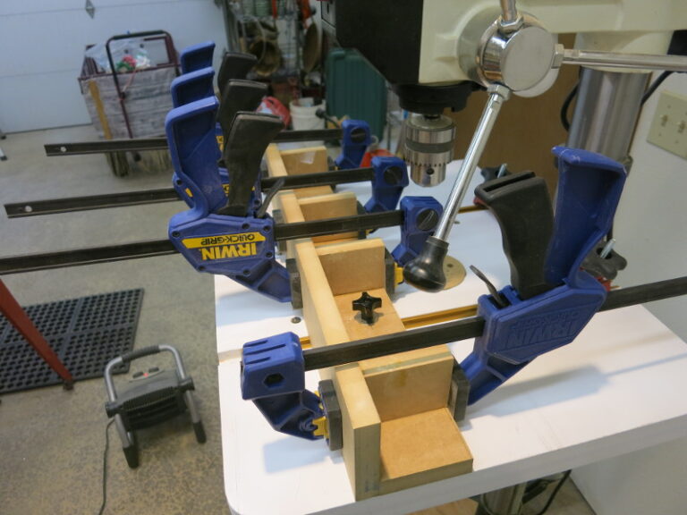
How to Make a Drill Press Fence
After completing my drill press table, I decided my next step would be to make a fence for it – so I can drill vertical holes in the sides of short boards.
First I cut a 3 1/2″ board of 3/4″ MDF, of a width to match the drill press table. This first piece will be the face of the fence.
Continue reading How to Make a Drill Press Fence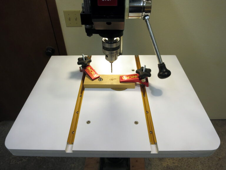
How to Make a Drill Press Table
As multiple woodworkers have mentioned, a drill press as-is is poorly suited to doing woodworking: the cast iron table can transfer grease to the wood; the table is small; the table has limited places to fasten clamps to hold the wood down.
So here I am making a drill press table.
Continue reading How to Make a Drill Press Table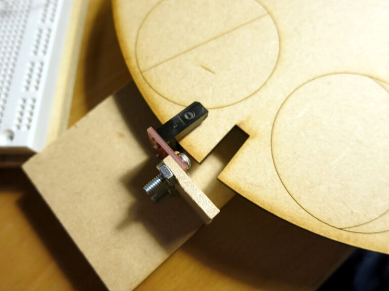
A Bit of the Mechanics of the Lunar Clock
I’ve been doing a bit of mechanical work on the lunar clock, that I started in my previous post.
As a prototype to help me design the laser-cut parts, I cut out a strip of 1/8″ MDF, cut a square for the motor’s shaft and two holes for the motor mounting holes, then mounted the motor to that strip of wood.
Continue reading A Bit of the Mechanics of the Lunar Clock