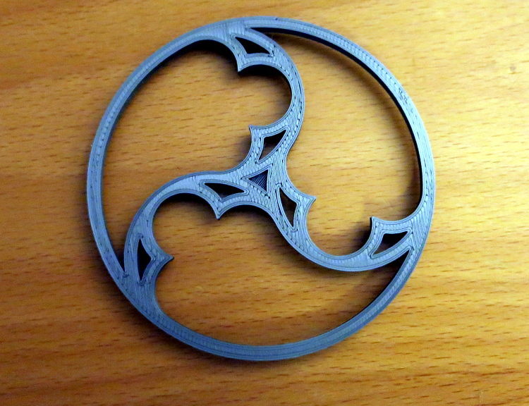
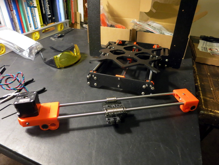
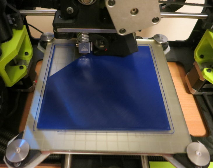
I find the rose windows of Gothic cathedrals awe-inspiring. From the rigid formalism of Chartres to the flamboyant explosion of Tours, their marriage of geometry, philosophy, and aesthetics with stone and glass is awesome. Built at a time when science and spirit weren’t as divided as today, each window is a statement of the beauty, order, and harmony in the world. Using only a pair of compasses (dividers) and a straight-edge (an unmarked ruler), the Gothic architects created myriad lace-like designs, making stone hang in the air and glass sing.
I often 3D print screw-top parts to replace broken or missing parts. For example, we recently installed media (blackout) shades for our skylights, so we can watch movies when the sun is out. Our family room ceiling is quite high, so the pole and hook designed to open and close the new shades is too short.
An idea’s been forming in the back of my head for a while: that it should be possible to estimate the amount of 3D filament left on a reel by simply weighing the reel with its filament, and subtracting the reel weight. Sounds simple, no?
Today I realized that it may be possible to modify a printer to give a live estimate of filament left on the currently-mounted reel, by “live weighing” the reel, and knowing the reel weight and filament density.
25 Lotus Flowers is a rotating-piece puzzle I recently invented (at least I’m ignorant of any earlier versions). The object is to turn the 25 lotus Flowers to form a given pattern. The challenge is that each Flower prevents one of its neighbors from turning, so you usually have to turn several Flowers before you can turn the one you want to turn.
I called the puzzle 25 Lotus Flowers because the 25 puzzle pieces look to me like ancient Egyptian images of lotus flowers, and the addictive nature of the puzzle reminds me of the Lotus Eaters in The Odyssey.
In my previous post, I replaced the electronics of my several-year-old lunar clock design with modern parts. In this post, I’ve replaced the laser cut parts with 3D printed parts, with particular attention to the clip that holds the photo interrupter in place.
In my previous post, I finished the Web Service that the ESP8266 uses to upload well tank temperatures (and eventually a depth estimate) to a cloud database. In this post, I turn to the mechanical design of the case for the RJ45 jacks for the 1-wire interface.
I’ve been interested in sundials for ages. Tracking the sun’s path by observing the shadow of a stick is an ancient form of astronomy, and a gateway into geometry (literally “land measurement”).
A sundial often marks the solstices and equinoxes, and enables measurement of the cardinal directions of north, south, east, and west: at the peak of its daily journey through the sky, the sun throws a north-south shadow; on the equinoxes, the shadow of the sun draws an east-west line. Ancient sundials acted as calendars, showing precisely when the sun returned to a given spot in its annual journey from south to north and back again.
Having read Clifford Smyth’s excellent book, Functional Design for 3D Printing, I was anxious to try out his method of cutting a design into parts and gluing those parts together after printing.
In my previous post, I did a little woodworking on the scale. In this post, I start designing a 3D printed part that will keep the top of the scale centered on the bottom.
Ever since I measured the center of gravity of the top plywood circle, I’ve been puzzling through how to make sure that center of gravity stays centered on the bottom part of the scale. Without some sort of connection between the top and bottom plywood circles, the top will inevitably slide over time, messing up all the center of gravity calculations. On the other hand, if this connection between the top and bottom has much vertical friction, it will take some of the load of the scale, throwing off the weight calculation.
In my previous post I soldered the weight scale parts to a proto-board. In this post, I design and 3D-print the part that keeps the Load Sensors from slipping.
The Load Sensor is an oddly-shaped thing that has a few tricky constraints: the T-shaped part in the middle must be free to bend downward (my wooden mounts take care of that), and I don’t want it to slide out of place horizontally or tilt off of its position when I’m putting the top plywood piece on the scale.